
Water Current Catcher System for Hydroelectricity Generation

Active Publication Date: 2019-08-29
GEHRING DONALD HOLLIS
View PDF49 Cites 0 Cited by
  • Summary
  • Abstract
  • Description
  • Claims
  • Application Information

AI Technical Summary

Benefits of technology

The present invention is a continuation-in-part of a patent application that claims a priority to a provisional application filed in July 2018. The invention is about a hydro-power generation system that uses a height adjustable waterwheel and a low-revolution per minute generator to convert the kinetic energy of flowing water into electrical energy. The invention aims to overcome the limitations of traditional waterwheels, such as large size, narrow width, and small paddles, and to provide a more efficient and cost-effective solution for generating energy from flowing water.

Problems solved by technology

However, the percentage of today's power supplied by hydro-electric power is declining and more power is being supplied by other forms of power generations such as wind and solar power.
As water levels decline, the head pressures on the turbines also declines along with the power outputs.
Since river, stream and tidal flow rates and water levels vary over time, it is difficult to maintain constant power production.
Large reservoirs often reduce power generation to maintain water levels.
New hydroelectric reservoir / power plant projects are fewer today in many parts of the developed world due to high cost of the projects compared to other new power plant alternatives, the increased regulations, increased environmental impact concerns, increased land costs, and increased competition from other viable low LCOE power plants, like wind, solar, gas, etc.
The biggest hurdle of the new hydroelectric reservoir / power plant projects can largely be attributed directly or indirectly to the significant amount of land that needs to be purchased and flooded to raise the water levels of the rivers to create the high water pressure jets needed for high RPM turbines and generators.

Method used


Image

  • Water Current Catcher System for Hydroelectricity Generation
  • Water Current Catcher System for Hydroelectricity Generation
  • Water Current Catcher System for Hydroelectricity Generation

Examples


second embodiment

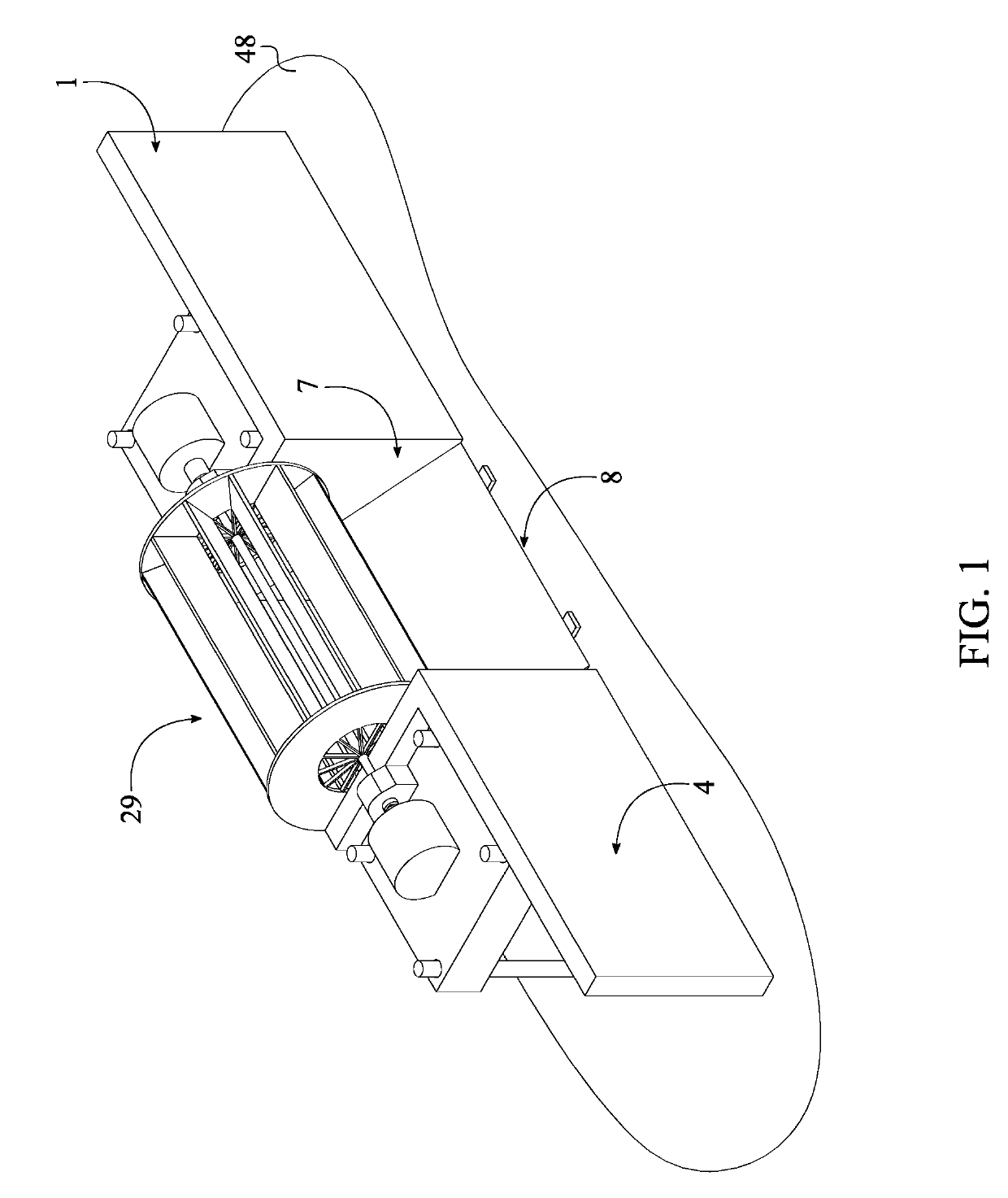
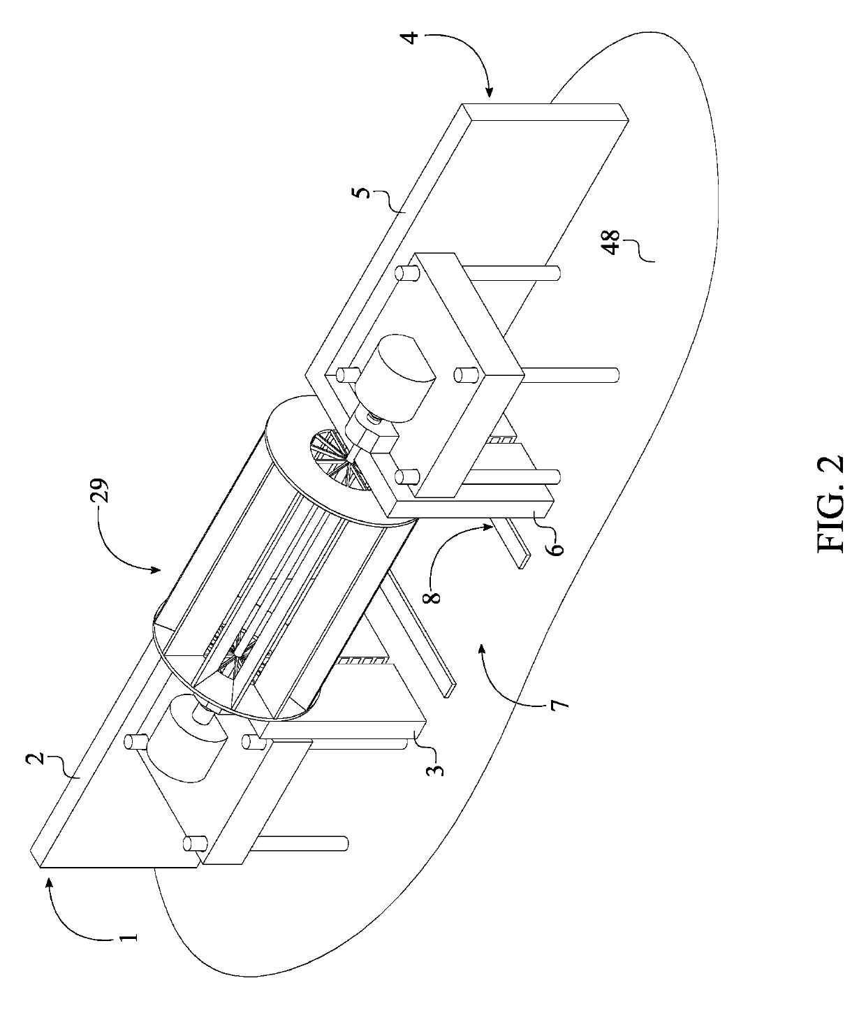
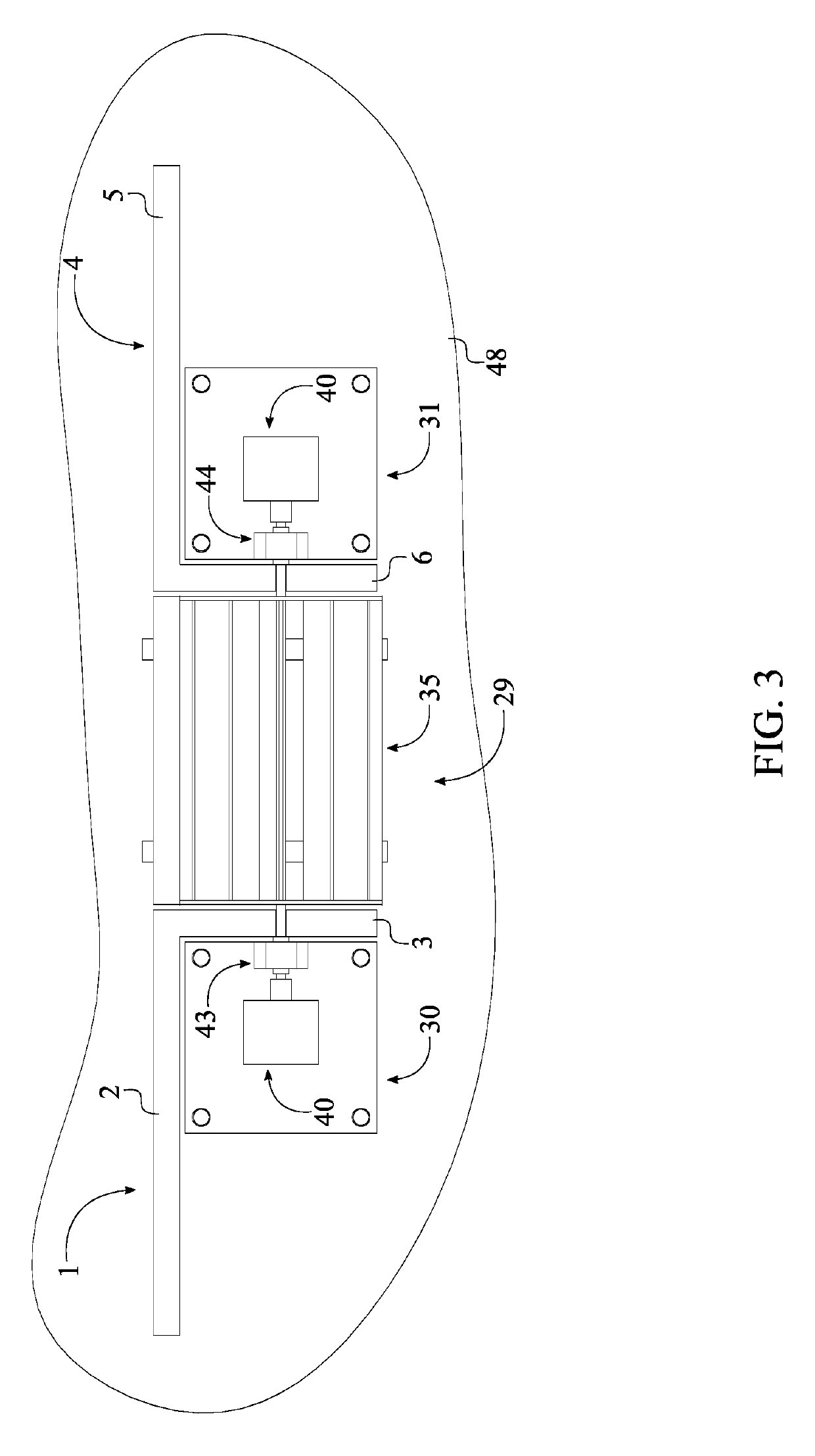
[0056]A second embodiment of the first gate operational mechanism 18 and the second gate operational mechanism 19 are configured similar to an inter-connected system. The functionality of the first gate operational mechanism 18 and the second gate operational mechanism 19 directly depend upon the support and the operation of the elevation adjustable hydroelectric generator unit 29. In reference to FIG. 13-14, the second embodiment of the first gate operational mechanism 18 and the second gate operational mechanism 19 each comprises a connector block 27 and a supported jacking system 28. More specifically, the gate hinge 13 is rotatably connected within the connector block 27 of the first gate operational mechanism 18 and the connector block 27 of the second gate operational mechanism 19. With respect to the first vertical slot 14, the supported jacking system 28 of the first gate operational mechanism 18 is terminally mounted in between the connector block 27 of the first gate opera...


PUM


Abstract

A water current catcher system for hydroelectricity generation includes a first L-shaped weir, a second L-shaped weir, a channel opening, an underwater gate assembly, and at least one elevation adjustable hydroelectric generator unit. The first and second L-shaped weir are connected to a subsurface environment and linearly positioned to each other. The channel opening is delineated between the first L-shaped weir and the second L-shaped weir. The underwater gate assembly is integrated into the first L-shaped weir, the second L-shaped weir, and the subsurface environment thus positioning about the channel opening. The elevation adjustable hydroelectric generator unit that includes a first jack-up barge, a second jack-up barge, a waterwheel, and a generator is connected to the subsurface environment and adjacently positioned about the channel opening. The elevation adjustable hydroelectric generator unit is operatively coupled with the underwater gate assembly to convert the kinetic energy of flowing water into hydroelectricity.

Description

[0001]The current application is a continuation-in-part (CIP) application of the U.S. non-provisional application Ser. No. 15 / 997,517 filed on Jun. 4, 2018. The U.S. non-provisional application Ser. No. 15 / 997,517 claims a priority to a U.S. provisional application Ser. No. 62 / 514,625 filed on Jun. 2, 2017.FIELD OF THE INVENTION[0002]The present invention relates generally to hydro-power generation. More specifically, the present invention utilizes a height adjustable waterwheel and highly efficient low revolution per minute generator to convert the kinetic energy of flowing water into electrical energy.BACKGROUND OF THE INVENTIONWaterwheels:[0003]For hundreds of years and before the advent of modern dams and associated very large water reservoirs, the power of flowing water was harnessed by a waterwheel. Most waterwheels were a relatively simple, relatively low cost, normally only used a portion of the river's flow and were usually located near one bank of the river and turned a ma...

Claims


Application Information

Patent Timeline
IPC IPC(8): F03B13/10F03B17/06
CPCF03B13/10F05B2240/302F05B2240/97F03B17/063F05B2240/915F03B13/264Y02E10/30
Inventor GEHRING, DONALD HOLLIS
Owner GEHRING DONALD HOLLIS
Features
  • Generate Ideas
  • Intellectual Property
  • Life Sciences
  • Materials
  • Tech Scout
  • Unparalleled Data Quality
  • Higher Quality Content
  • 60% Fewer Hallucinations
Learn More