
Bridge type river and tide water-power and wind-power combined power generation corridor

A technology for combined power generation and wind power generation, which is used in hydropower, hydropower stations, tidal flow/damless hydropower, etc., and can solve problems such as dam collapse, ineffective use of hydropower, and harmful ecological environment.

Inactive Publication Date: 2014-08-20
朱华
View PDF12 Cites 27 Cited by
  • Summary
  • Abstract
  • Description
  • Claims
  • Application Information

AI Technical Summary

Problems solved by technology

[0002] The existing wind power generation still uses the three-leaf power generation technology with vertical rods and horizontal axes. The existing hydropower generation still uses the traditional power generation technology of damming and storing water. The three-leaf power generation technology cannot effectively utilize wind power. In addition to the inability to effectively utilize water power, the dam-building water storage power generation technology is also harmful to the ecological environment and there is also the worry of dam collapse. my country has not only abundant wind power resources, but also abundant water power resources. There are thousands of rivers and rivers that can use hydraulic power, and the huge water flows that flow into the rivers can be used. In my country's more than 3 million square kilometers of sea area, there are not only tens of thousands of islands and reefs, but also more than 30,000 kilometers of coastal waterlines. Develop tidal hydro wind power

Method used

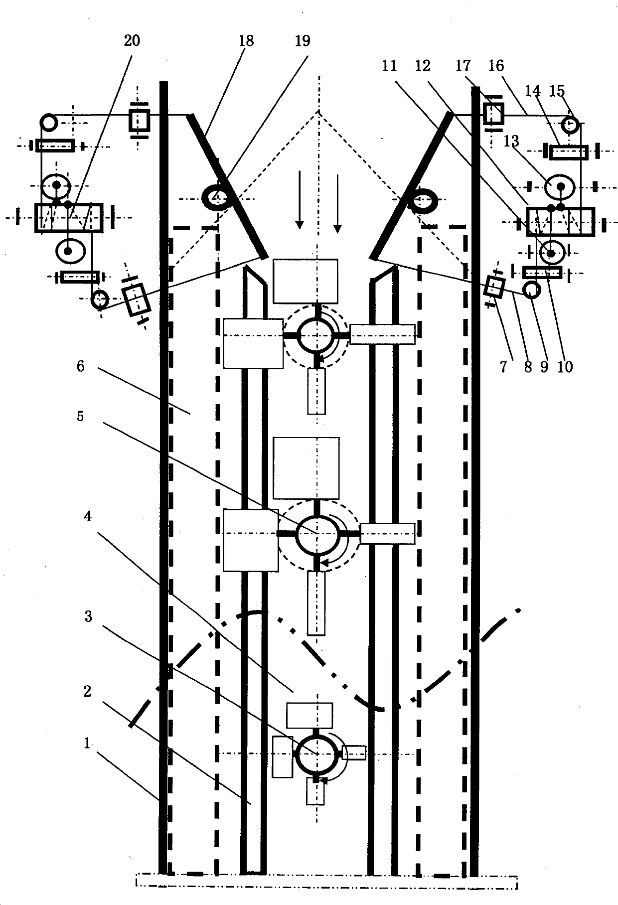
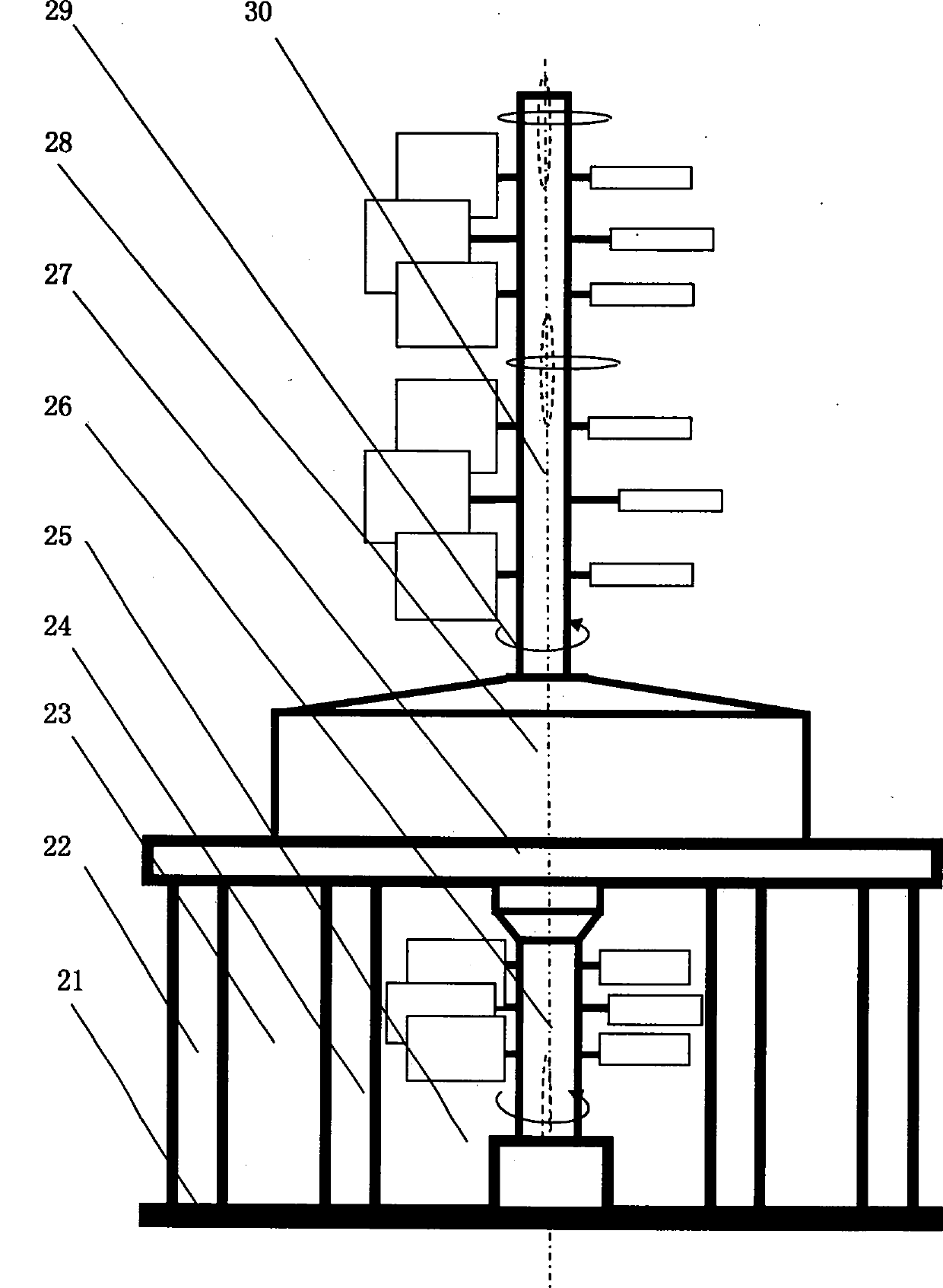
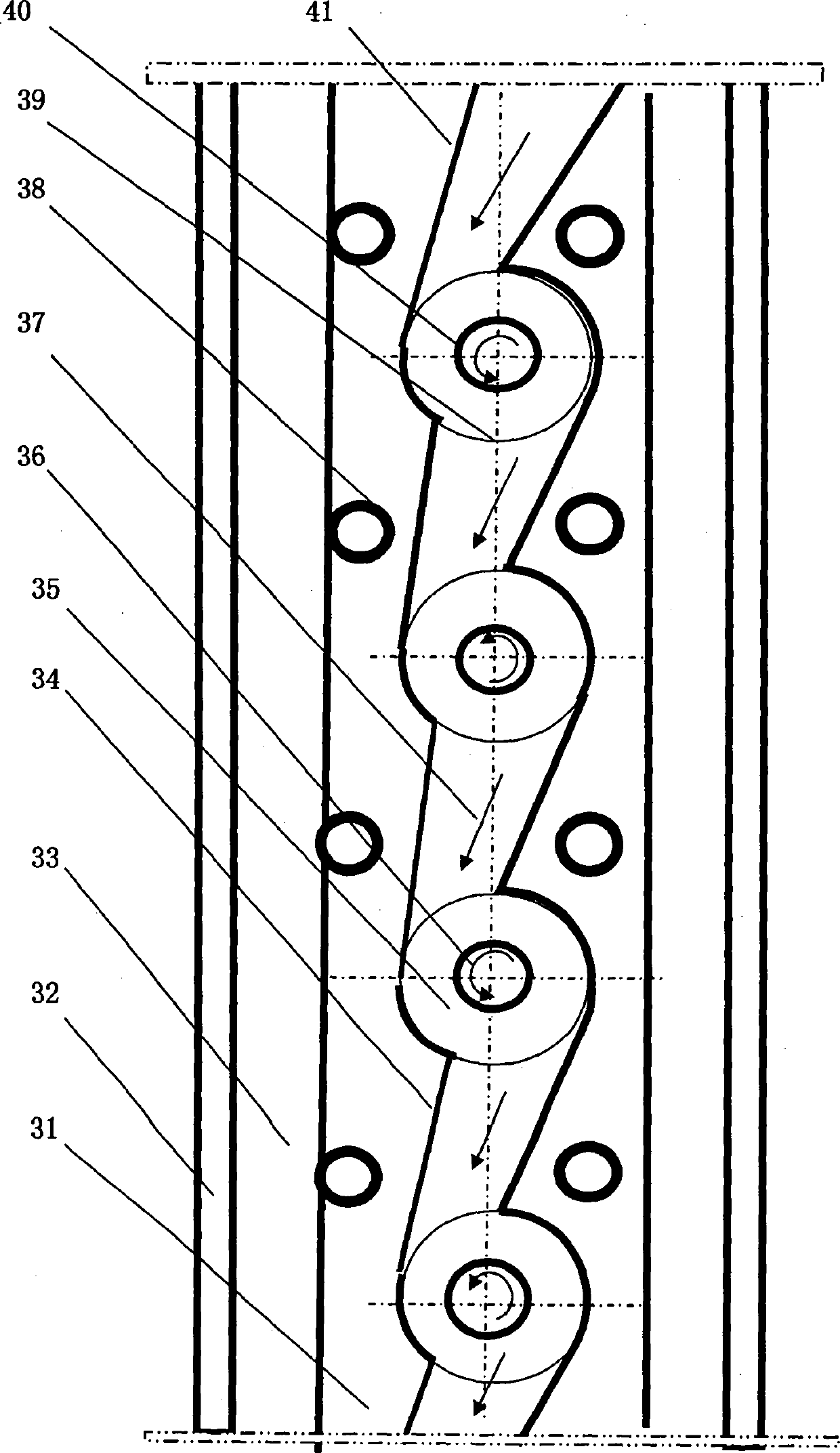

Image

  • Bridge type river and tide water-power and wind-power combined power generation corridor
  • Bridge type river and tide water-power and wind-power combined power generation corridor
  • Bridge type river and tide water-power and wind-power combined power generation corridor

Examples


Embodiment Construction

[0015] Below in conjunction with embodiment for further description

[0016] exist figure 1In the center of the river, the full-bridge river hydro-wind power generation promenade is constructed with two straight-through vertical diversion dikes (2) to form a hydropower channel (4). A cross-river bridge deck is built on the two diversion embankments (2) of the channel (4), and a tree-like hydroelectric power generation device (3) is built in the hydropower generation channel (4) under the bridge deck, corresponding to the tree-like hydropower generation device on the bridge deck (3) at the position, build a tree-shaped wind power generating device (5), the transmission shaft of the upper and lower power generating device (5) (3) on the bridge plate is connected into one, and the wind-inducing blades on the upper and lower power generating device (5) (3) transmission shaft Arranged in the same direction of rotation as the 'water-attracting blades', the wind-inducing blades caus...


PUM


Abstract

A bridge type river and tide water-power and wind-power combined power generation corridor is composed of a full-bridge type river water-power and wind-power combined power generation corridor, a shore bridge type river water-power and wind-power combined power generation corridor and a bridge type tide water-power and wind-power combined power generation corridor which are respectively a combiner of a tree-shaped wind power generation device (1) built on a bridge plate and a tree-shaped water power generation device built below the bridge plate. In order to effectively utilize the abundant water power resources and the wind power resources in China, the bridge type river water power, tide water power and wind power combined power generation technology is provided, the bridge type river water power, tide water power and wind power combined power generation corridor is built by combining the river water power with tide water power and wind power so that natural energy can be effectively utilized for power generation, more electric energy is provided for people, and the degree of dependence on underground resources such as petroleum and coal is decreased.

Description

technical field [0001] The invention belongs to the technical field of natural energy utilization, and is a technology for centralized power generation by utilizing hydropower and wind power, which is a bridge-type river tidal hydro-wind power combined power generation corridor. Background technique [0002] The existing wind power generation still uses the three-leaf power generation technology with vertical rods and horizontal axes. The existing hydropower generation still uses the traditional power generation technology of damming and storing water. The three-leaf power generation technology cannot effectively utilize wind power. In addition to the inability to effectively utilize water power, the dam-building water storage power generation technology is also harmful to the ecological environment and there is also the worry of dam collapse. my country has not only abundant wind power resources, but also abundant water power resources. There are thousands of rivers and river...

Claims


Application Information

Patent Timeline
IPC IPC(8): E02B9/08F03D9/02F03B13/26
CPCY02E10/28Y02E10/72Y02E10/30
Inventor 朱华
Owner 朱华
Learn More