Multi-level dc bus inverter for providing sinusoidal and PWM electrical machine voltages

a dc bus and inverter technology, applied in the direction of dc-ac conversion without reversal, dynamo-electric converter control, multiple dynamo-motor starters, etc., can solve the problem of increasing the number of active switches and achieve the effect of reducing the number of switches

Inactive Publication Date: 2005-11-29
UT BATTELLE LLC
View PDF7 Cites 82 Cited by
  • Summary
  • Abstract
  • Description
  • Claims
  • Application Information

AI Technical Summary

Benefits of technology

[0005]Compared to the cascaded H-bridge, diode-clamped and flying capacitor multi-level inverters, the multi-level dc bus inverters with full bridge networks of commutation switches can significantly reduce the power semiconductor switch count as the number of voltage levels increases beyond five. For a given number of voltage levels, m, the required number of active switches is 2×(m−1) for the existing multi-level inverters, but is m+3 for the multi-level dc bus inverters.

Problems solved by technology

A technical problem is that as the number of dc voltage levels, m, grows, the number of active switches increases according to 2×(m−1) for the cascaded H-bridge, diode-clamped and flying capacitor multi-level inverters.

Method used


Image

  • Multi-level dc bus inverter for providing sinusoidal and PWM electrical machine voltages
  • Multi-level dc bus inverter for providing sinusoidal and PWM electrical machine voltages
  • Multi-level dc bus inverter for providing sinusoidal and PWM electrical machine voltages

Examples


Embodiment Construction

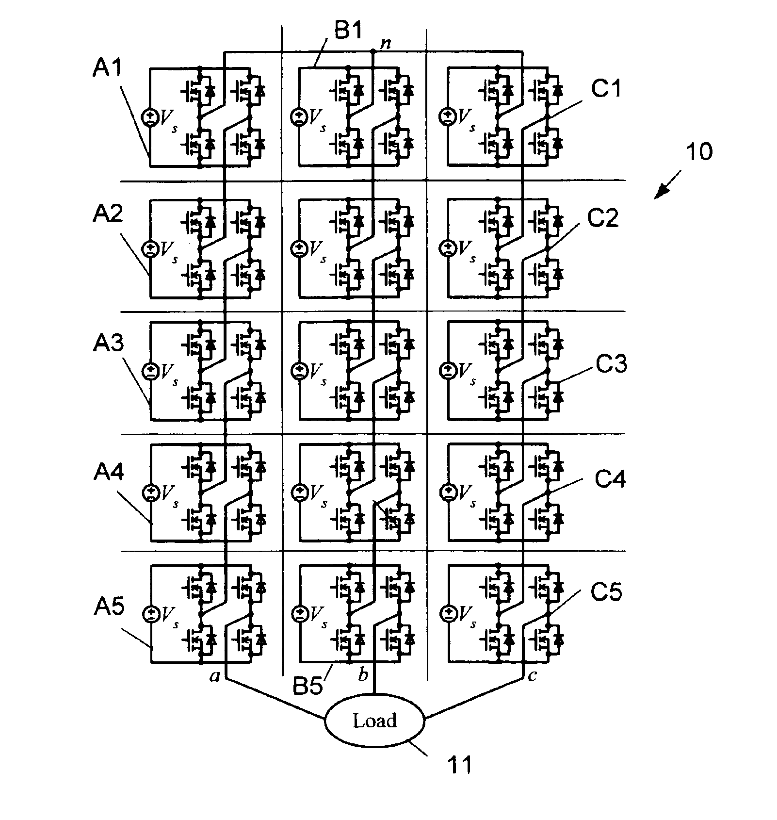
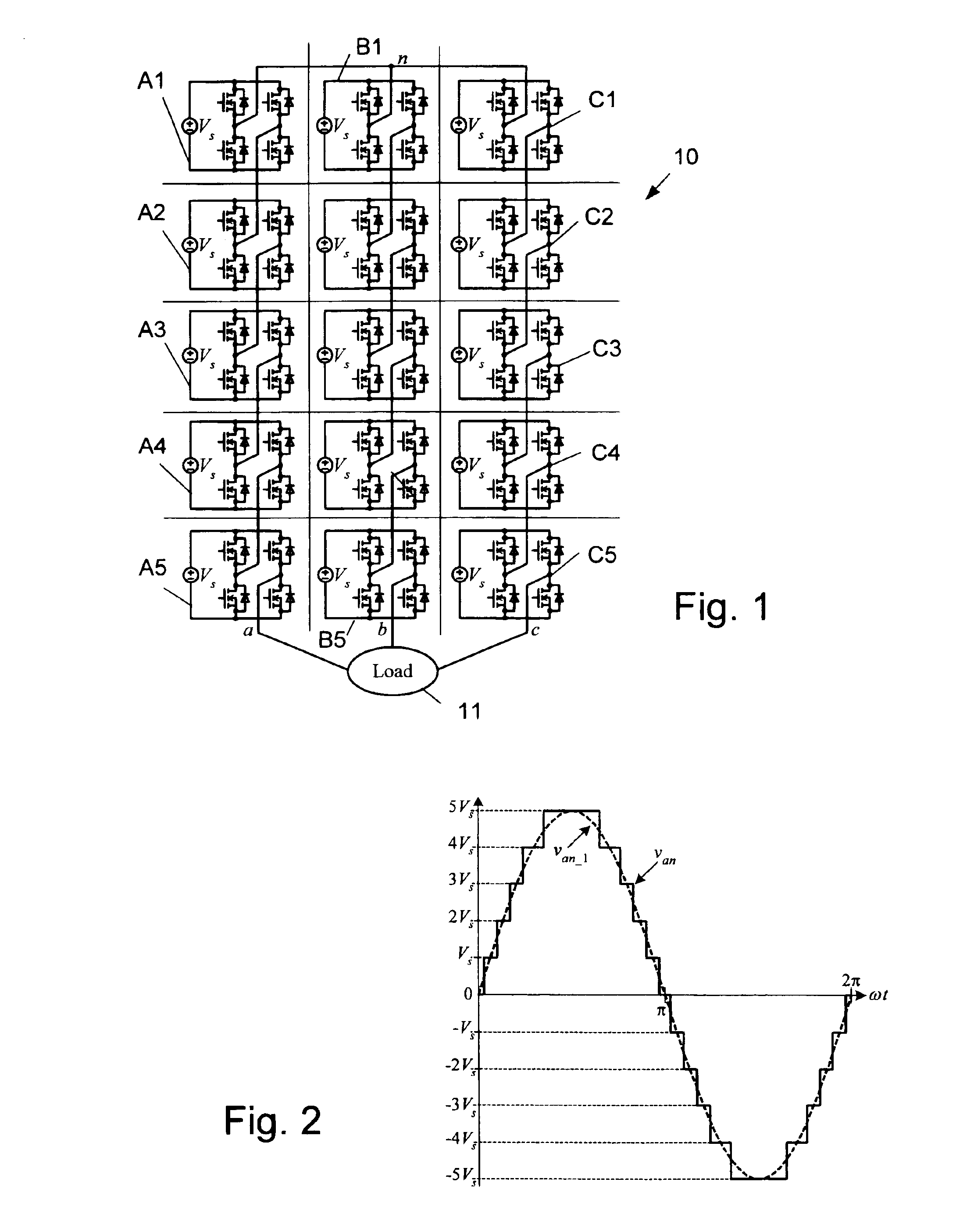
[0036]FIG. 1 shows the power circuit 10 for a three-phase, Y-connected cascaded H-bridge inverter with five cells A1-A5, B1-B5 and C1-C5 in each respective phase a, b and c for supplying a load 11. The phase voltage is synthesized by the addition of the voltages generated by each cell, which can have one of three values: −Vs, 0, or Vs. As seen in FIG. 2, the resulting phase voltage, Van has a staircase shape of eleven levels, 5Vs, 4Vs, 3Vs, 2Vs, Vs, 0, −Vs, −2Vs, −3Vs, −4Vs, −5Vs, to approximate a sinusoidal voltage, van—1.

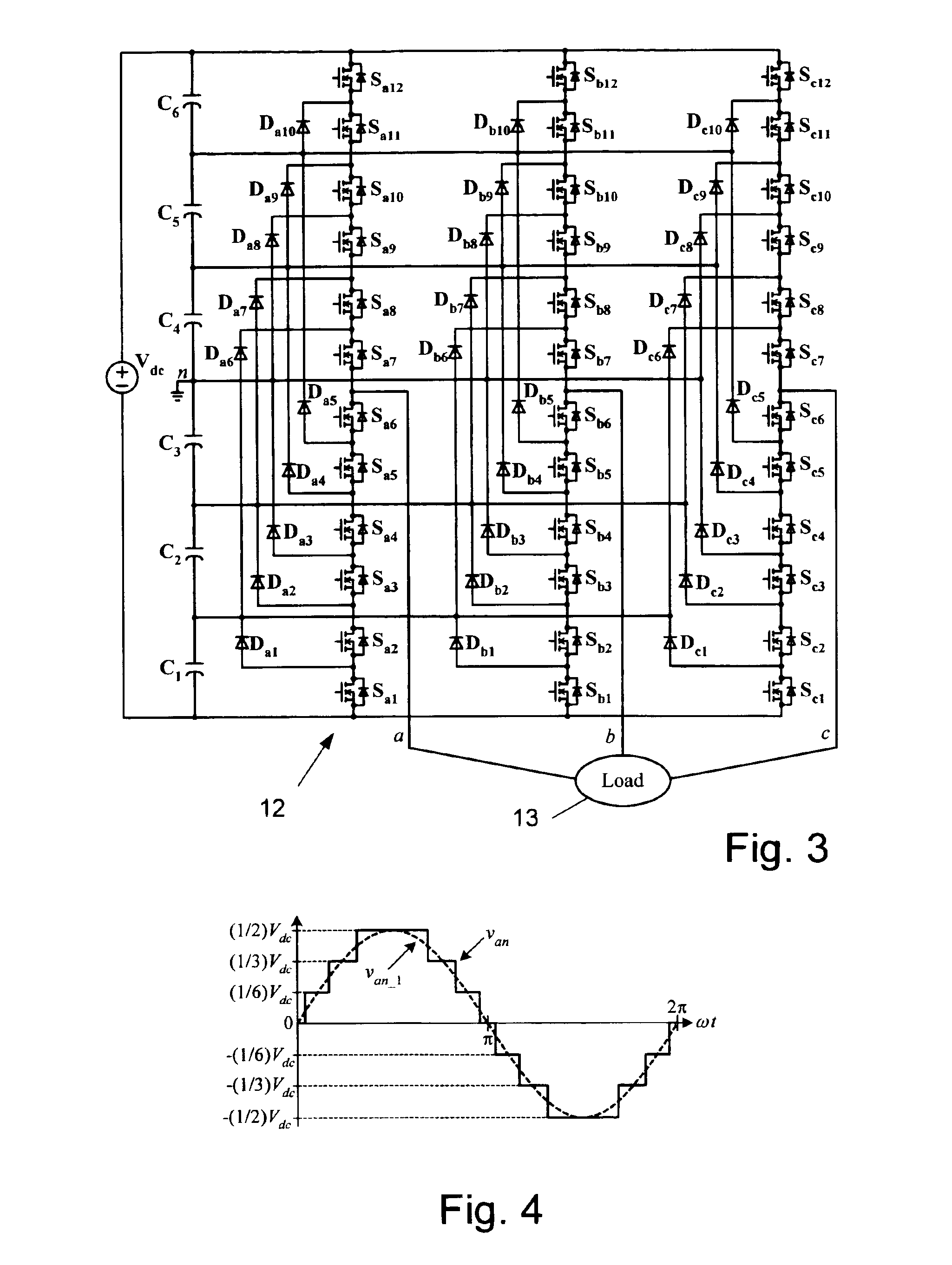
[0037]FIG. 3 illustrates a seven-level diode-clamped inverter 12 for supplying a load 13. In this circuit 12, the dc source voltage, VdC is split into six levels by six series-connected capacitors, C1-C6. Defining the middle point of the capacitors n as the zero-reference point for the phase voltages and assuming the dc source voltage, VdC is evenly divided by the capacitors, the inverter can produce staircase-shaped phase voltages of seven levels: Vdc / 2, Vdc / 3, V...


PUM


Abstract

A circuit for controlling an ac machine comprises a full bridge network of commutation switches which are connected to supply current for a corresponding voltage phase to the stator windings, a plurality of diodes, each in parallel connection to a respective one of the commutation switches, a plurality of dc source connections providing a multi-level dc bus for the full bridge network of commutation switches to produce sinusoidal voltages or PWM signals, and a controller connected for control of said dc source connections and said full bridge network of commutation switches to output substantially sinusoidal voltages to the stator windings. With the invention, the number of semiconductor switches is reduced to m+3 for a multi-level dc bus having m levels. A method of machine control is also disclosed.

Description

STATEMENT REGARDING FEDERALLY SPONSORED RESEARCH[0001]This invention was made with Government support under Contract No. DE-AC05-00OR22725 awarded to UT-Battelle, LLC, by the U.S. Department of Energy. The Government has certain rights in this invention.TECHNICAL FIELD[0002]The field of the invention is single-phase and polyphase ac machines, including both motors and generators.DESCRIPTION OF THE BACKGROUND ART[0003]Traditionally, two-level inverters with GTOs (gate turn-off thyristors) were the choice for medium- and high-voltage level applications such as motor drives and static VAR (reactive power) compensation. Multi-level inverters using IGBTs (insulated gate bipolar transistors) have been proposed for replacing the GTO-based two-level inverters in medium-voltage applications. Because IGBTs can switch faster and have less demanding gate drive requirements than GTOs, inverters with these devices can significantly reduce the size and weight of passive filter components and offer...

Claims


Application Information

Patent Timeline
Patent Type & Authority Patents(United States)
IPC IPC(8): H02M7/48H02M7/487
CPCH02M7/487H02M7/49H02M2001/007H02M1/007H02M7/4835H02M1/0095H02M7/4837
Inventor SU, GUI-JIA
Owner UT BATTELLE LLC
Why Eureka
Try Eureka