Inline hydro electric generation system

a hydroelectric generation system and hydroelectric technology, applied in the direction of electric generator control, control system, climate sustainability, etc., can solve the problems of many failures, inability to meet the cost effective deliverable of technology, and huge research and development costs, so as to facilitate the rotation of the drive shaft, avoid water loss, and maintain constant water pressure

Inactive Publication Date: 2010-12-09
GLOBAL ENVIORNMENTAL ENERGY SOLUTIONS INC
View PDF13 Cites 29 Cited by
  • Summary
  • Abstract
  • Description
  • Claims
  • Application Information

AI Technical Summary

Benefits of technology

[0014]In another embodiment of the present invention, the housing may include an inlet attachment point and an outlet attachment point that are capable of rigidly connecting to the water pipe. The inlet and outlet attachment points may be retrofitted to the water pipe via unions so that the water flows through the housing resulting in no water loss while sustaining a constant water pressure. The housing may further include an outer housing cover that substantially covers an upper portion of the impeller. The outer housing may be removed to provide access to the open space.
[0015]In another embodiment of the present invention, the impeller blades may have leading and trailing ends wherein the leading end is rounded. In addition, the body of an impeller blade may be configured to have grooves. The impeller blades may further be configured ...

Problems solved by technology

With some successes come many failures, especially with proposed ‘new’ technologies.
The expense researching new energy technologies is monumental and they generally fail to meet the cost effective deliverables of the technology.
As a result, researchers have gone a short distance with the greatest expense ever seen in the energy industry.
At present, energy technologies fail to cater to areas where electrical power is not readily available.
In this regard, remote locations are not provided with a reliable and effective power source.
There are numerous situations where electrical power is not readily available, such as in the immediate aftermath of a natural disaster or at a remote location.
Additionally, many energy technologies are not environmentally friendly.
In this regard, the construction of dams and power plants are harmful to the environment.
However, traditional water wheels suffer from many disadvantages.
Most importantly, they must be located near an uninterrupted source of water to function.
In addition, ice, debris, and imbalance of the wheel may negatively affect th...

Method used


Image

  • Inline hydro electric generation system
  • Inline hydro electric generation system
  • Inline hydro electric generation system

Examples


Embodiment Construction

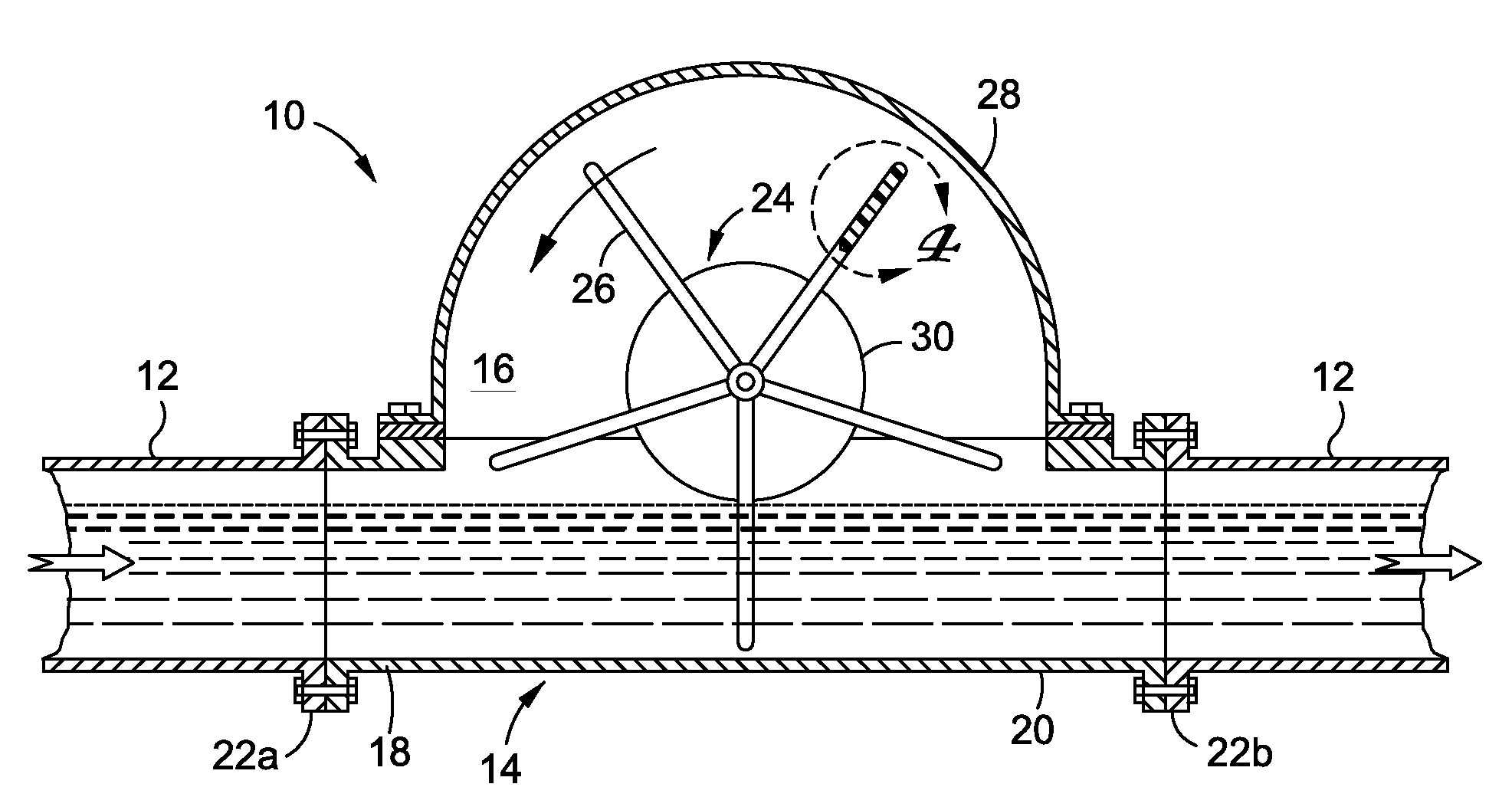
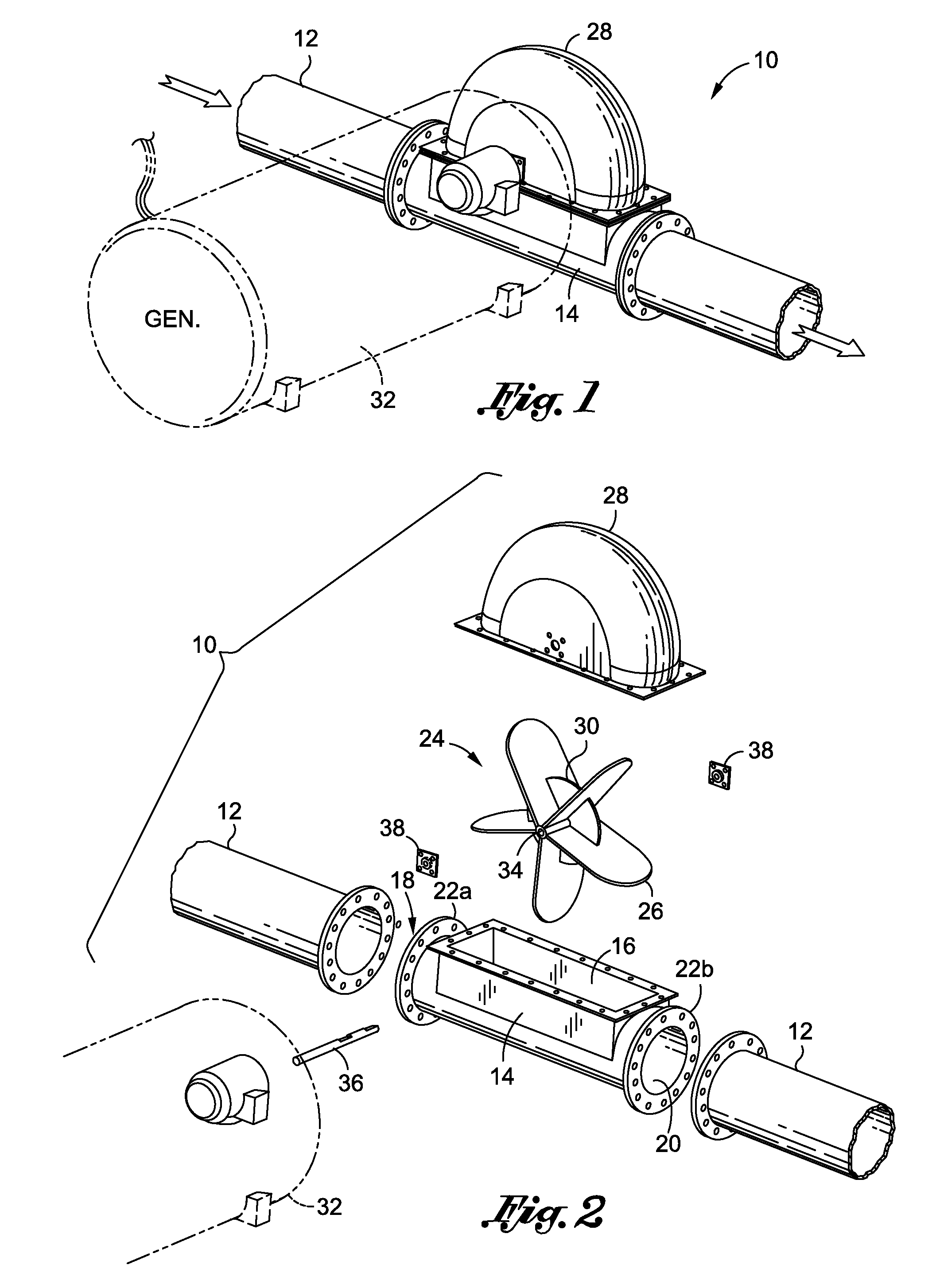
[0026]Referring now to the drawings wherein the showings are for purposes of illustration various embodiments of the present invention only, and not for purposes of limiting the same, FIGS. 1 and 2 depict an inline hydro electric generation system 10 constructed in accordance with the present invention. The inline hydro electric generation system 10 is an integrated system that utilizes existing water delivery systems as an energy source to generate electrical power. In the present embodiment the water delivery system is a conventional in ground water pipe 12. However, it is contemplated that the inline hydro electric generation system may be adapted to work with a variety of water delivery systems including a variety of water pipes such as in ground pipes, above ground pipes, water pipes that are housed in structures, and the like.

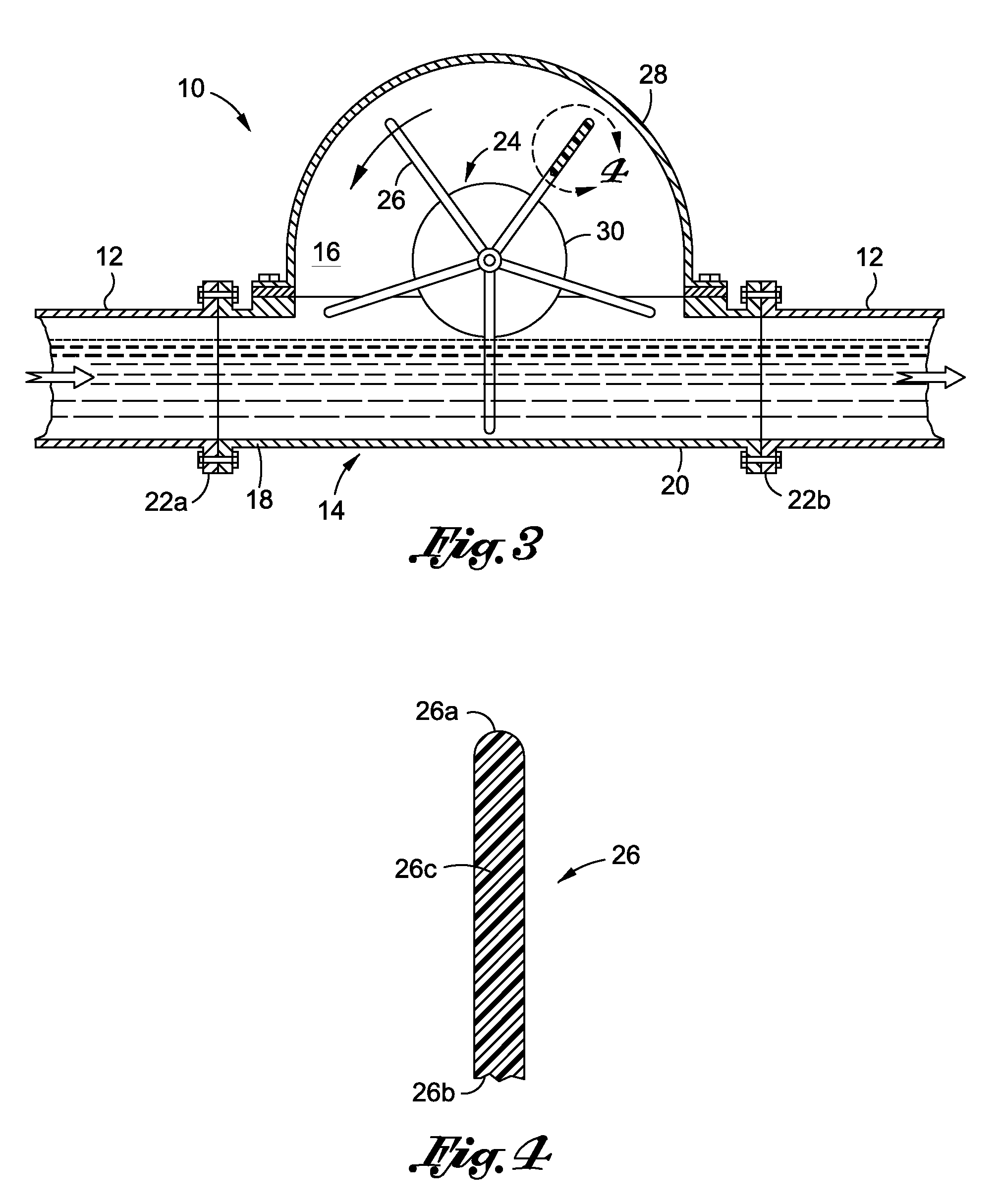
[0027]The inline hydro electric generation system 10 comprises a housing 14 defining an internal open space 16 with at least one opposed inlet 18 and out...


PUM


Abstract

An inline hydro electric generation system for harnessing the potential energy of water passing in existing water pipes is provided. The inline hydro electric generation system comprises a housing upon which a rotatable impeller with a plurality of impeller blades is mounted. The housing is affixed to a water pipe so that water passes from the water pipe into the housing subsequently initiating the impeller to mechanically rotate. The impeller is advantageously designed so that only one impeller blade is submerged under water as the impeller is mechanically rotated. An electrical generator is axially coupled to the impeller so that when the impeller rotates, the electrical generator generates electrical power. Subsequently, the water is departs from the housing and is returned into the water pipe to continue its route to its intended recipients. The inline hydro electric generation system provides a low cost and environmentally friendly alternative to conventional energy generation systems.

Description

CROSS-REFERENCE TO RELATED APPLICATIONS[0001]Not ApplicableSTATEMENT RE: FEDERALLY SPONSORED RESEARCH / DEVELOPMENT[0002]Not ApplicableBACKGROUND[0003]1. Field of the Invention[0004]The present invention pertains to water-driven electrical generators and, more particularly to an inline hydro electric generation system for generating power by harnessing the energy from water running in existing water pipes.[0005]2. Description of the Related Art[0006]Today, energy is a primary concern for all businesses and communities around the world. Every industrial nation is currently searching for new innovative means to generate and utilize energy. In this regard, vast resources are being invested in researching and developing new and alternative methods to enhance future energy generation. Currently, billions of dollars are being spent daily in this quest for energy. The magnitude of the increased energy demand, coupled with the infusion of this money has been the driving incentive that has con...

Claims


Application Information

Patent Timeline
IPC IPC(8): F03B13/00
CPCF03B13/00F05B2220/20Y02B10/50F05B2220/604F05B2220/70642F05B2220/602
Inventor GODFREY, CARL L.
Owner GLOBAL ENVIORNMENTAL ENERGY SOLUTIONS INC
Why Eureka
Try Eureka