
Pitch drive device capable of emergency operation for a wind or water power plant

a technology of pitch drive and emergency operation, which is applied in the direction of electric generator control, renewable energy generation, greenhouse gas reduction, etc., can solve the problems of pitch drive failure risk and severe reduction of torque, and achieve fast emergency movement or adjustment of rotors, high torque, and high torque

Active Publication Date: 2013-01-24
MOOG UNNA GMBH +1
View PDF4 Cites 28 Cited by
  • Summary
  • Abstract
  • Description
  • Claims
  • Application Information

AI Technical Summary

Benefits of technology

The invention proposes a wind or water power plant pitch drive device that can emergency operate to adjust the rotor blade. The device includes an inverter and a three-phase current drive motor. The motor is a permanent-magnet-excited three-phase current IPM synchronous motor, which can provide higher torque than a conventional motor when the supply voltage drops, such as in a failure. This increases the robustness of the rotor blade adjustment device and improves the safety of the energy plant. The device also includes an energy storage device that can directly supply energy to the motor to control its rotational speed, even when the intermediate circuit voltage drops. This ensures that the motor can operate safely and efficiently even in emergency situations.

Problems solved by technology

In the event of a failure of a power system supply, the direct voltage energy storage device usually cannot maintain the high level of the intermediate circuit voltage of 560 V DC, with the result that the direct voltage VZK can drop to 100 V as a function of the energy consumption by the pitch drive and of the storage capacity.
In this situation, conventional SPM (Surface Permanent Magnet) synchronous motors can only be subjected to rotational speed control inadequately and within narrow limits, their torque experiences a severe reduction and there is a high risk of the pitch drive failing.

Method used


Image

  • Pitch drive device capable of emergency operation for a wind or water power plant
  • Pitch drive device capable of emergency operation for a wind or water power plant
  • Pitch drive device capable of emergency operation for a wind or water power plant

Examples


Embodiment Construction

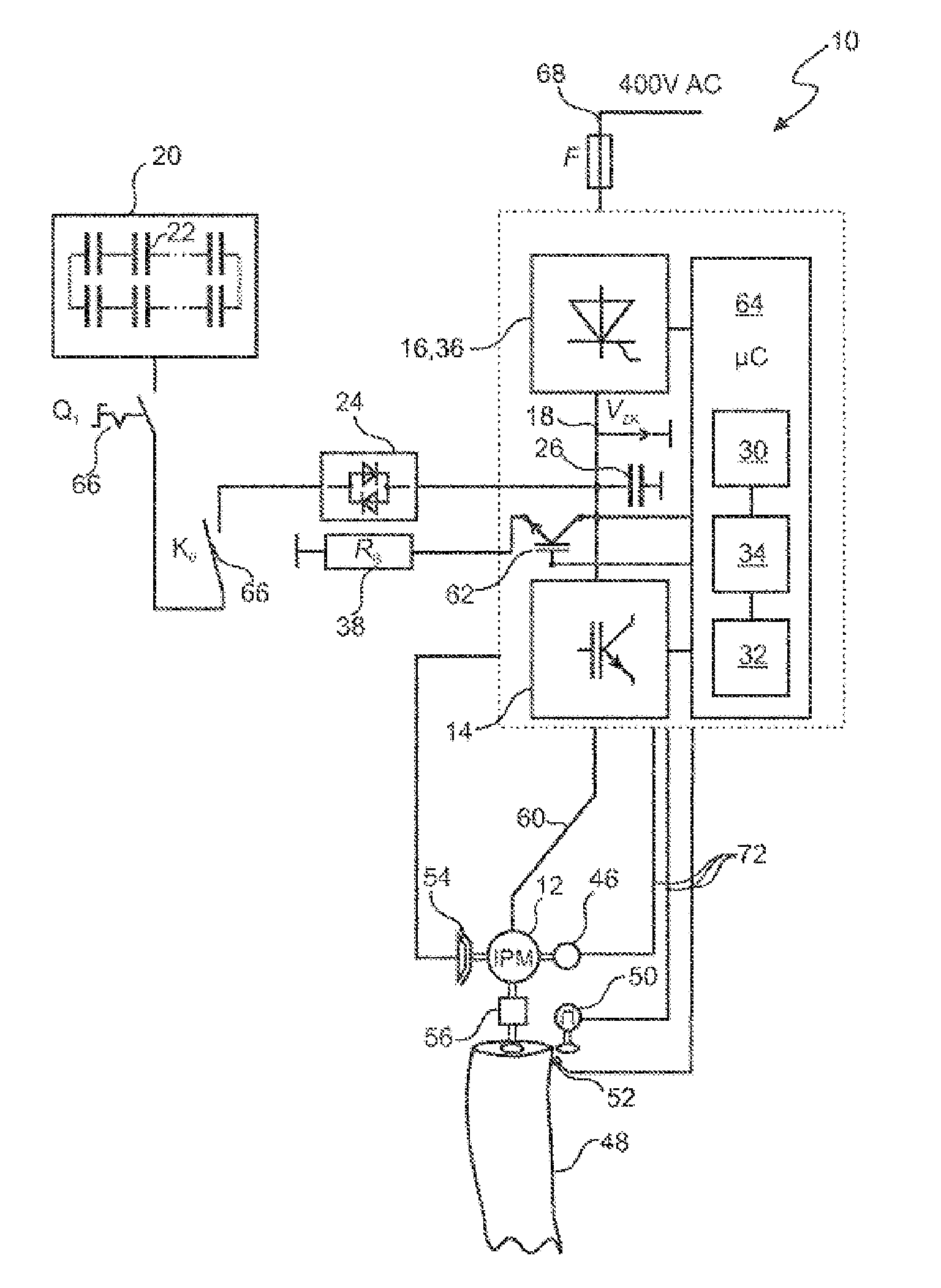
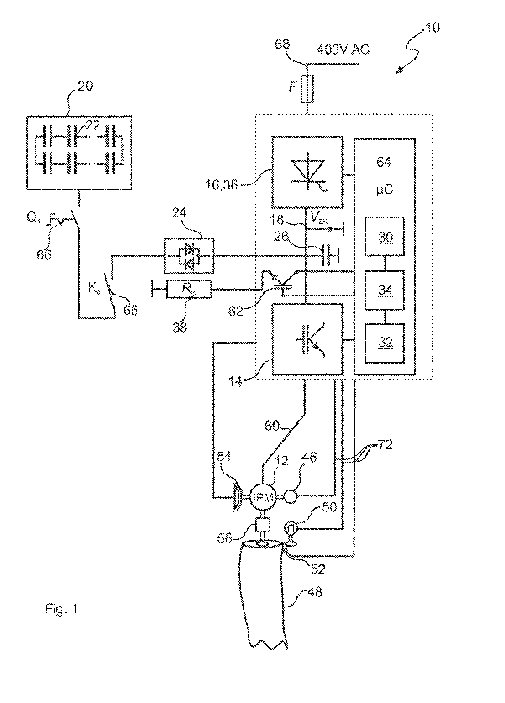
[0067]Identical components or components of the same type are denoted by identical reference signs in the figures. The following diagrams serve to provide schematic illustration, and therefore, for example, a connecting line signifies an electrical connection between two electrical devices and as a rule comprises at least one forward line and one return line. Switching symbols represent not only individual components but also a circuit assembly which can comprise one or more components.

[0068]FIG. 1 is a schematic representation of a first exemplary embodiment of a pitch drive device 10 according to the invention. The pitch drive device 10 comprises a synchronous motor 12, which is embodied as an IPM motor, as well as a direct voltage energy storage device 20 and an inverter device 14, which actuates the motor 12 via a PWM (Pulse Width Modulation) motor actuation line 60 by means of a motor control device 64, in order to set a desired rotor blade adjustment of a rotor blade 48.

[0069]...


PUM


Abstract

A pitch drive device capable of emergency operation by adjusting the rotor blade pitch of a wind or water power plant. The pitch drive device includes an inverter device and a three-phase current drive motor preferably a three-phase IPM synchronous motor. A direct current power storage device can be substantially directly connected to an intermediate direct current circuit, at least for emergency operation, between a rectifier device and the inverter device for at least briefly supplying power to the synchronous motor, so that the IPM synchronous motor can be operated under speed control when the intermediate circuit voltage UZK is falling. The device enables speed-controlled emergency operation of the pitch drive device at high torque when an intermediate circuit voltage UZK is falling in emergency operation, wherein the direct current energy storage device can, improve the efficiency as an energy buffer, and reduce current transfer via the rotor slip ring.

Description

PRIOR ART[0001]The present invention relates to a pitch drive device capable of emergency operation for adjusting a rotor blade pitch of a wind or water power plant.[0002]Devices of the generic type serve to change a pitch angle (pitch) with respect to a flowing medium of air or water of a rotor blade in order to drive an energy generating device, in particular a power generator.[0003]The prior art has disclosed the use of DC and AC asynchronous motors (ASM) in electromechanical drive systems to adjust the rotor blade of a rotor of a wind or water power plant which can be controlled as a function of the rotational speed. DC machines are used since they permit emergency movement of the rotor blade into a vane position even in the event of a failure of control electronics and power electronics, wherein an accumulator pack or battery pack supplies the direct voltage in the event of a power system failure. AC machines are frequently used since they are virtually maintenance-free and are...

Claims


Application Information

Patent Timeline
Patent Type & Authority Applications(United States)
IPC IPC(8): H02P9/04
CPCF03B15/00F03D7/0224F05B2260/76F05B2260/79H02P27/08F05B2270/1074Y02E10/226Y02E10/721Y02E10/723F05B2270/107Y02E10/20Y02E10/72
Inventor ROESMANN, TOBIASKAUKE, LARS
Owner MOOG UNNA GMBH
Learn More