Eureka AIR delivers breakthrough ideas for toughest innovation challenges, trusted by R&D personnel around the world.

Clip Having A Thermal Insulation Layer

Inactive Publication Date: 2019-08-29
NORMA GERMANY GMBH
View PDF7 Cites 0 Cited by
  • Summary
  • Abstract
  • Description
  • Claims
  • Application Information

AI Technical Summary

Benefits of technology

The invention is a clip with good thermal insulation that can reduce heat loss and protect surrounding parts from heat damage. The clip has a simple and cost-effective design, with a thermal insulation layer ranging from 0.1 to 3 mm thick.

Problems solved by technology

In particular, long exhaust gas systems are sometimes present in truck engines, which would lead to significant heat loss without corresponding thermal insulation.
However, the connecting elements used, in particular clips, frequently have no thermal insulation whatsoever so that significant heat losses occur in these regions.
Additionally, heat-sensitive components may be damaged by a high level of heat dissipation from the connecting elements.

Method used


Image

  • Clip Having A Thermal Insulation Layer

Examples


Embodiment Construction

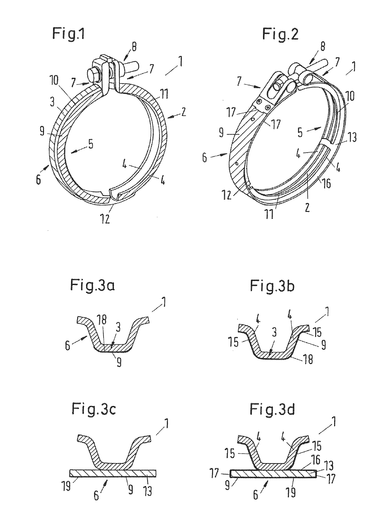
[0037]FIG. 1 shows a clip 1 according to an embodiment with a clip band 2, which has a base 3 and two radially inwardly directed flanks 4. In the embodiment shown here, the clip band 2 has a trapezoidal profile. The clip 1 has an inner face 5 which is formed by the inner face of the base 3 and the flanks 4, and an outer face 6 which is formed by the outer face of the base 3 and the flanks 4. The ends 7 of the clip band 2 are connected together, clamped and fastened via a clamping device 8. In the example shown here the clamping device 8 has a screw with a screw head and a screw connection. The outer face 6 of the clip 1 has a thermal insulation layer 9 which in this case covers both the flanks 4 and the base 3. Here the thermal insulation layer is a non-positive coating of the outer face 6 of the clip 1.

[0038]The embodiment shown in FIG. 1 has two clip portions 10, 11 which are connected together via a joint portion 12.

[0039]In FIG. 2 an alternative embodiment of the clip is shown. ...


PUM


Abstract

The disclosure relates to a clip, in particular a ring clip, that includes a clip band, which has a base and two radially inwardly directed flanks, and at least one clamping device, wherein the clip has an inner face and an outer face. According to the disclosure, the outer face of the clip has at least a partial thermal insulation layer.

Description

INTRODUCTION[0001]The disclosure relates to a clip.[0002]Clips, in particular ring clips, are used, for example, for connecting two components, wherein each of the components to be connected has a radially outwardly directed flange on the end side. For the connection, typically the two flanges are brought into contact and a clip is positioned thereon, so that the inner faces of the flanks of a clip bear against the rear faces of the flanges. The clamping and fastening of the clip and thus the connection take place subsequently by means of the clamping device.[0003]A clip which is suitable therefor is disclosed, for example, in DE 10 2009 039 862 B4.[0004]Pipelines which are connected to other components by means of clips are also fitted, for example, in the engine compartments of passenger motor vehicles and trucks. In the context of more efficient and more environmentally friendly engines, high temperatures of the exhaust gases are often desirable during the post-treatment, so that...

Claims


Application Information

Patent Timeline
IPC IPC(8): F16L23/08F01N13/14
CPCF01N13/14F16L23/08F01N13/16F01N13/1855F01N2510/02F16L59/184
Inventor HOPPE, MARVIN
Owner NORMA GERMANY GMBH
Why Eureka
Eureka Blog
Learn More