Mixing vessel with locking assembly for locking a mixing assembly in storage position and mixing impeller with central disc-like member

a technology of locking assembly and mixing impeller, which is applied in the direction of mixers, mixer accessories, mixing, etc., can solve the problems the danger of mixing fluid, and the inability of the mixing impeller to rotate, so as to prevent the rotational movement of the mixing impeller. , the effect of preventing the rotational movement of the mixing impeller

Active Publication Date: 2019-09-05
SARTORIUS STEDIM BIOTECH GMBH
View PDF2 Cites 0 Cited by
  • Summary
  • Abstract
  • Description
  • Claims
  • Application Information

AI Technical Summary

Benefits of technology

[0032]The shape and / or size of the recess of the mounting depression shall correspond to the shape and / or size of the protrusion of the mixing impeller such that the protrusion may perfectly fit into the recess. Thus, any rotational movement of the mixing impeller is prevented.
[0078]If the disc-like member is conical to the top of the disc-like member or dome-shaped, liquid is further prevented from resting on the top of the disc-like member when draining the singe-use mixing vessel. The high value of biological material means that holdup (i.e. leftover material which cannot be removed from the single-use mixing vessel) is to be avoided at all costs.

Problems solved by technology

Some applications require that the mixing equipment is fully closed with no possibility of leakage between the mixing vessel and the environment—for example, the fluids to be mixed are either hazardous (e.g. toxic) or if they are sensitive to contamination from the outside environment (e.g. highly purified pharmaceutical material).
In other words, the mixing impeller is not able to rotate.
Levitating movements of the mixing impeller are then no longer possible.
For powder dissolution, however, a large quantity of powder is added through a port at the top of the single-use mixing vessel.
Powder that becomes trapped in a gap between the mixing impeller and a side wall of the mounting depression of the mixing vessel might render the mixing impeller unable to start.
Accordingly, a further technical problem is to provide a mixing impeller for mixing components, which enables a reliable powder dissolution.

Method used


Image

  • Mixing vessel with locking assembly for locking a mixing assembly in storage position and mixing impeller with central disc-like member
  • Mixing vessel with locking assembly for locking a mixing assembly in storage position and mixing impeller with central disc-like member
  • Mixing vessel with locking assembly for locking a mixing assembly in storage position and mixing impeller with central disc-like member

Examples


Embodiment Construction

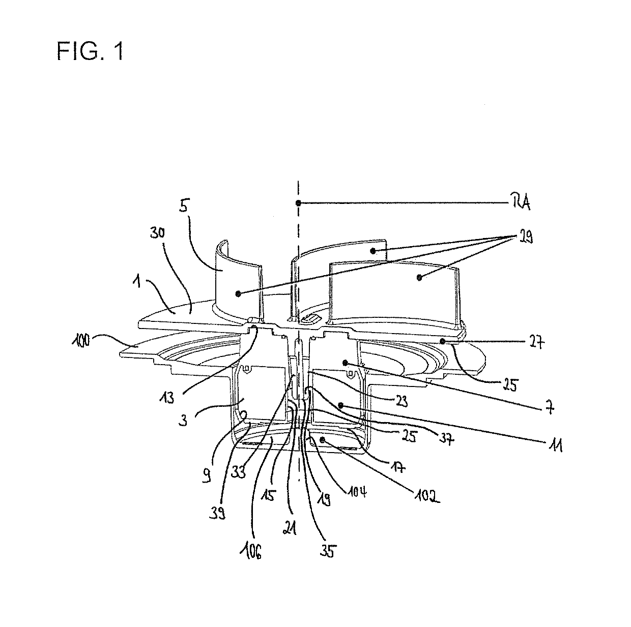
[0080]FIG. 1 Is a cross-sectional perspective view of a mixing impeller being inserted in a mounting depression of a mixing vessel.

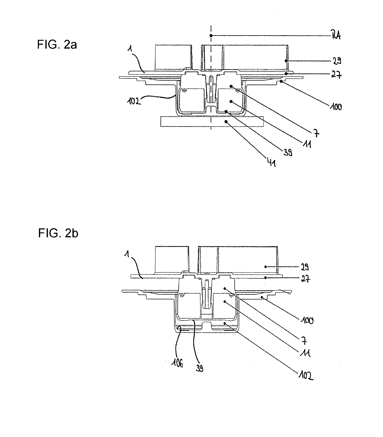
[0081]FIG. 2a is a cross-sectional view of the mixing impeller of FIG. 1 with the mixing impeller in the storage position.

[0082]FIG. 2b is a cross-sectional view of the mixing impeller of FIG. 1 with the mixing impeller in the mixing position.

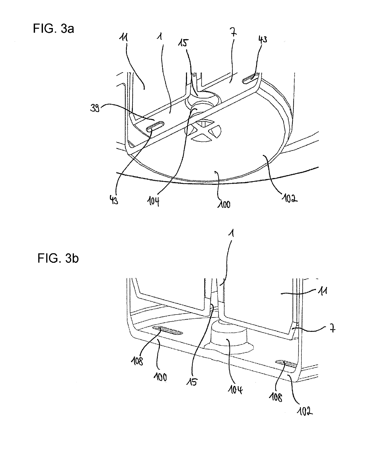
[0083]FIG. 3a is a cross-sectional perspective view showing the mixing impeller inserted in the mounting depression and oriented to show the bottom of the mixing impeller and showing a first option for additionally blocking rotational movement of the mixing impeller in the storage position.

[0084]FIG. 3b is a cross-sectional perspective view showing the mixing impeller inserted in the mounting depression and oriented to show the bottom of the mounting depression of FIG. 3a.

[0085]FIG. 4a is a cross-sectional perspective view similar to FIG. 3b, but showing a second option for additionally blocking a rotational moveme...


PUM


Abstract

A mixing vessel for accommodating components to be mixed has a container with at least one mounting depression in a side wall of the container. The mounting depression is adapted so that a mixing impeller housing of a mixing impeller is at least partly insertable, in which at least one magnet is housed for being magnetically connectable to a drive device to be driven. A locking assembly is attachable to the mounting depression from outside for locking the mixing impeller in a storage position, in which the mixing impeller is not rotatable. The locking assembly has a magnetically active element that is adapted to interact with the magnet of the mixing impeller.

Description

[0001]The present application is a divisional application of U.S. patent application Ser. No. 15 / 010,260, filed Jan. 29, 2016, the contents of which are hereby incorporated by reference in their entirety.BACKGROUND1. Field of the Invention[0002]The invention relates to a mixing vessel for accommodating components to be mixed. The mixing vessel includes means to lock a mixing impeller in a storage position. The invention also relates to a system comprising the mixing vessel, the mixing impeller and the means to lock the mixing impeller in the storage position, and further to a mixing impeller and a method for assembling.2. Related Art[0003]In the conventional engineering practice, a mixing device comprises a mixing vessel containing components to be mixed and a motor rotating a mixing impeller such that the components are mixed.[0004]Some applications require that the mixing equipment is fully closed with no possibility of leakage between the mixing vessel and the environment—for exa...

Claims


Application Information

Patent Timeline
Patent Type & Authority Applications(United States)
IPC IPC(8): B01F7/00B01F15/00B01F13/08B01F7/22B01F27/91
CPCB01F7/00208B01F15/0085B01F13/0827B01F15/00876B01F15/00662B01F7/22B01F7/00341B01F33/453B01F35/513B01F27/091B01F27/91B01F27/113B01F35/40B01F35/53
Inventor BOETTCHER, LARSCUTTING, JONATHAN E.WEST, SHARON D.OSCHWALD, MARTINBATES, MIKE
Owner SARTORIUS STEDIM BIOTECH GMBH
Why Eureka
Try Eureka