
Multiscale Deformation Measurements Leveraging Tailorable and Multispectral Speckle Patterns

a multi-spectral speckle pattern and deformation measurement technology, applied in the direction of optical apparatus testing, image enhancement, instruments, etc., can solve the problems of installation, operation and maintenance of a network, time and cost issues, and affect the aesthetic appearance of the inspected structur

Active Publication Date: 2019-09-05
DREXEL UNIV
View PDF4 Cites 20 Cited by
  • Summary
  • Abstract
  • Description
  • Claims
  • Application Information

AI Technical Summary

Benefits of technology

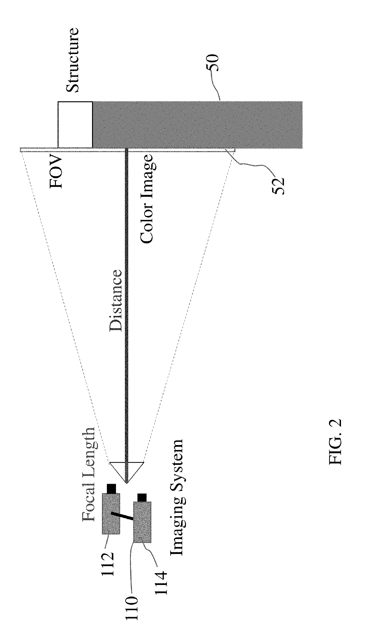
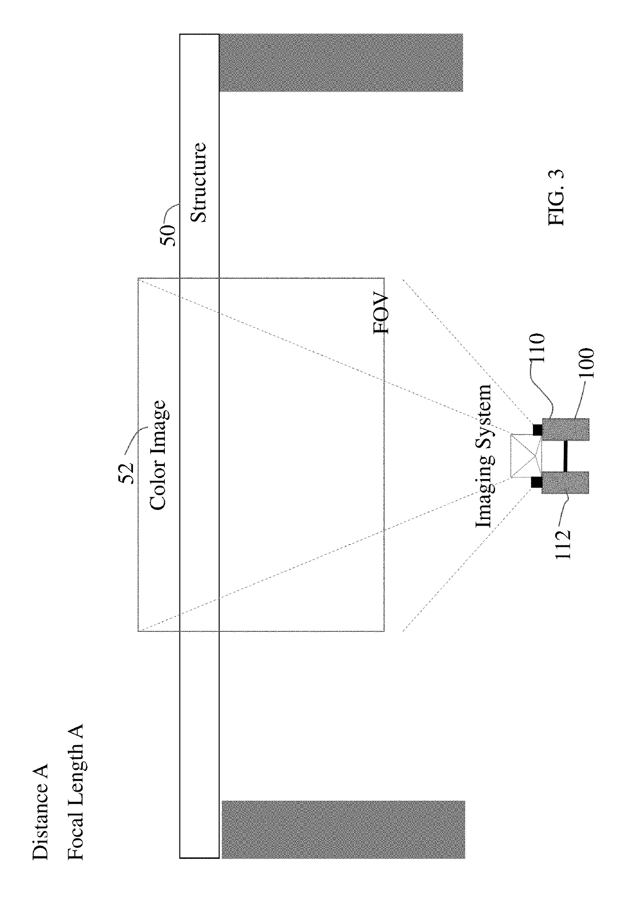
The invention is a system that uses special techniques to remotely measure changes in the structure of objects using image data. This is accomplished by collecting information from optical markers placed on the objects and combining it with information from special patterns in the image. This system can measure deformation at different distances and at different levels of detail, making it very versatile and useful for a variety of applications.

Problems solved by technology

It is often difficult, however, to install, operate and maintain a network of such sensors which results into both time and cost issues.
A potential issue, however, with applying speckle patterns for single or multiscale measurements in the visible spectrum is that they potentially affect negatively the aesthetic appearance of the inspected structure in addition to also interfere with other concurrent assessments, for example discoloration observations associated with corrosion.
Moreover, overlaying finer speckles within regions already covered in coarser speckles hinder the ability to detect deformation within the coarser zones.

Method used


Image

  • Multiscale Deformation Measurements Leveraging Tailorable and Multispectral Speckle Patterns
  • Multiscale Deformation Measurements Leveraging Tailorable and Multispectral Speckle Patterns
  • Multiscale Deformation Measurements Leveraging Tailorable and Multispectral Speckle Patterns

Examples


Embodiment Construction

[0048]In the drawings, like numerals indicate like elements throughout. Certain terminology is used herein for convenience only and is not to be taken as a limitation on the present invention. The terminology includes the words specifically mentioned, derivatives thereof and words of similar import. The embodiments illustrated below are not intended to be exhaustive or to limit the invention to the precise form disclosed. These embodiments are chosen and described to best explain the principle of the invention and its application and practical use and to enable others skilled in the art to best utilize the invention.

[0049]Reference herein to “one embodiment” or “an embodiment” means that a particular feature, structure, or characteristic described in connection with the embodiment can be included in at least one embodiment of the invention. The appearances of the phrase “in one embodiment” in various places in the specification are not necessarily all referring to the same embodimen...


PUM

PropertyMeasurementUnit
temperaturesaaaaaaaaaa
diameteraaaaaaaaaa
diameteraaaaaaaaaa

Abstract

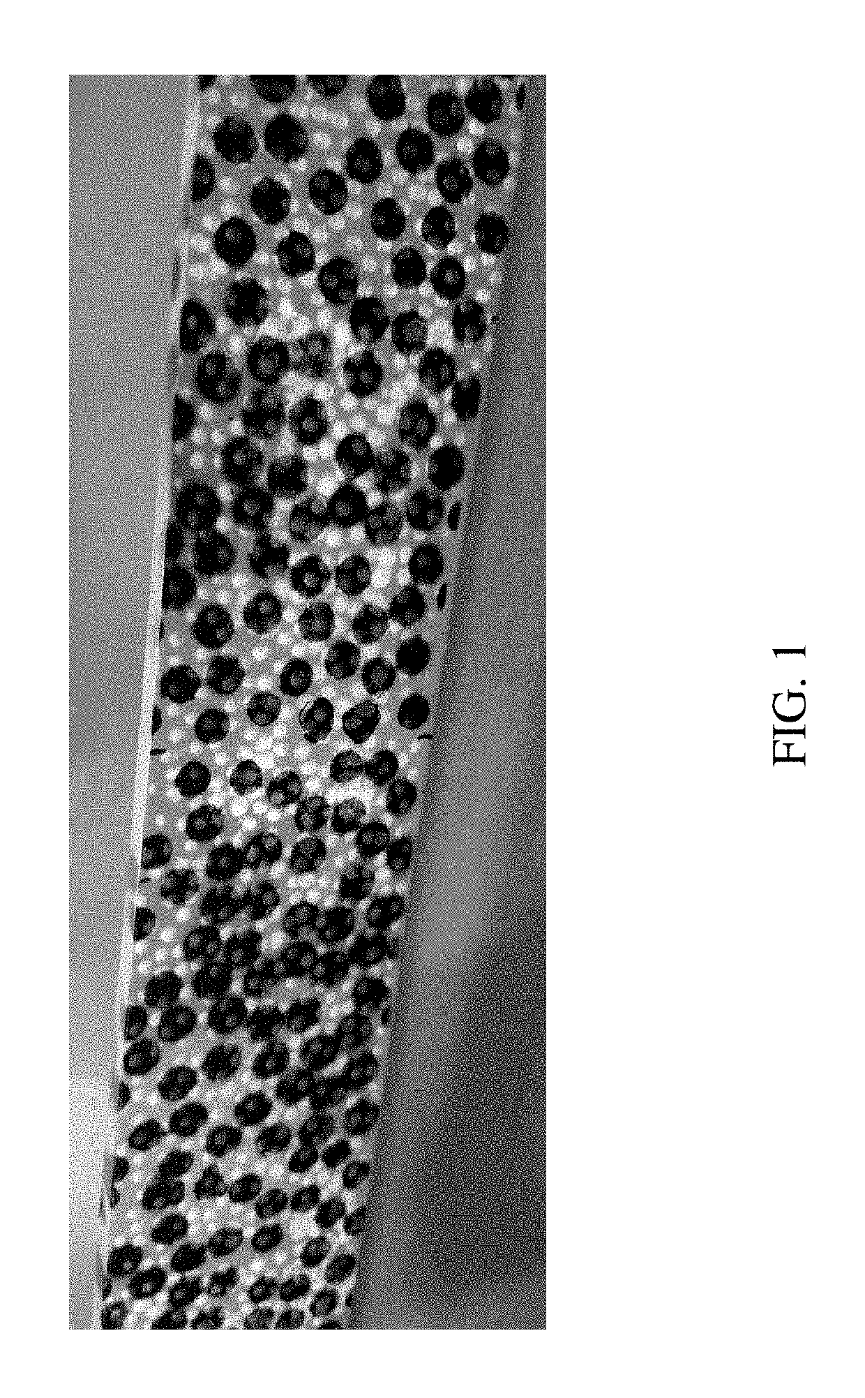
Remote measurements using images are particularly useful in structural health monitoring cases in which the installation of contact sensors is difficult. Some limitations, though, associated with photogrammetry-type optical metrology involve the application of speckle patterns, which become even more important with variable working distance or when the required resolution and sensitivity are not a priori known. In this context, multispectral sensing combined with tailored speckle patterns can circumvent some of the challenges of acquiring data at different working distances. The present invention uses multispectral imaging combined controlled generation of speckle patterns to demonstrate an approach for remote sensing related to deformation measurements at the structural level. To demonstrate this approach, two speckle patterns were designed for measurements at specified working distances. The results show that the spectral specific reflectivity of the speckle patterns allow for spatial overlay without affecting imaging within either spectral range considered, which results in the extraction of multiscale deformation measurements.

Description

CROSS-REFERENCE TO RELATED APPLICATION[0001]This application claims the benefit of U.S. Provisional Patent application Ser. No. 62 / 637,454, filed on Mar. 2, 2018, which is incorporated herein by reference in its entirety.STATEMENT OF GOVERNMENT INTEREST[0002]This invention was made with government support under Contract No. 1538389 awarded by the National Science Foundation. The government has certain rights in the invention.BACKGROUND OF THE INVENTION[0003]Deformation measurements on materials and structures across length scales are currently obtained routinely by using contact sensing methods such as displacement and strain gauges, as well as fiber optics among others. These sensing methods typically provide high accuracy data that can be used to assess, for example, the state of structural health. It is often difficult, however, to install, operate and maintain a network of such sensors which results into both time and cost issues. In this context, several other methodologies inc...

Claims


Application Information

Patent Timeline
Patent Type & Authority Applications(United States)
IPC IPC(8): G01B11/16G06T7/00G01N21/93G01N21/47G01N21/956
CPCG01B11/162G01B11/167G06T7/001G01N21/93G01N2021/479G01N21/95607G06T2207/10036G01N2021/95615G01N21/4788G01B11/16G01M5/0075G01M11/081G06T2207/10024G06T7/521G06T7/593
Inventor KONTSOS, ANTONIOSMELVIN DOMIN MATHEW, FNUELLENBERG, ANDREW JAMESBARTOLI, IVAN
Owner DREXEL UNIV
Learn More