Scanning laser ophthalmoscope

a laser ophthalmoscope and scanning technology, applied in the field of scanning laser ophthalmoscopes, can solve the problems of abnormal end, limited up range, and inability to properly perform ocular examination or image capture, and achieve the effect of suppressing eye movement and stable imag

Inactive Publication Date: 2019-09-12
LASER
View PDF0 Cites 1 Cited by
  • Summary
  • Abstract
  • Description
  • Claims
  • Application Information

AI Technical Summary

Benefits of technology

[0014]With such a configuration, the fundus image of the eye of the subject can be obtained by using the first laser light having the wavelength in the infrared range and the eye of the subject can recognize th...

Problems solved by technology

However, since the above-mentioned contacting means is not configured to completely fix the head of the subject with respect to the device, the eye of the subject (the head of the subject) may move during the ocular examination or image capturing.
In this case, the ocular examination or the image capturing ...

Method used


Image

  • Scanning laser ophthalmoscope
  • Scanning laser ophthalmoscope
  • Scanning laser ophthalmoscope

Examples


Embodiment Construction

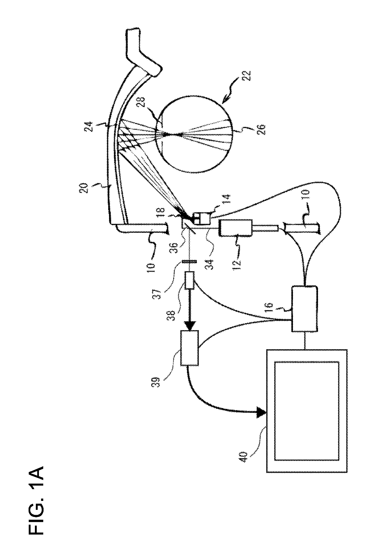
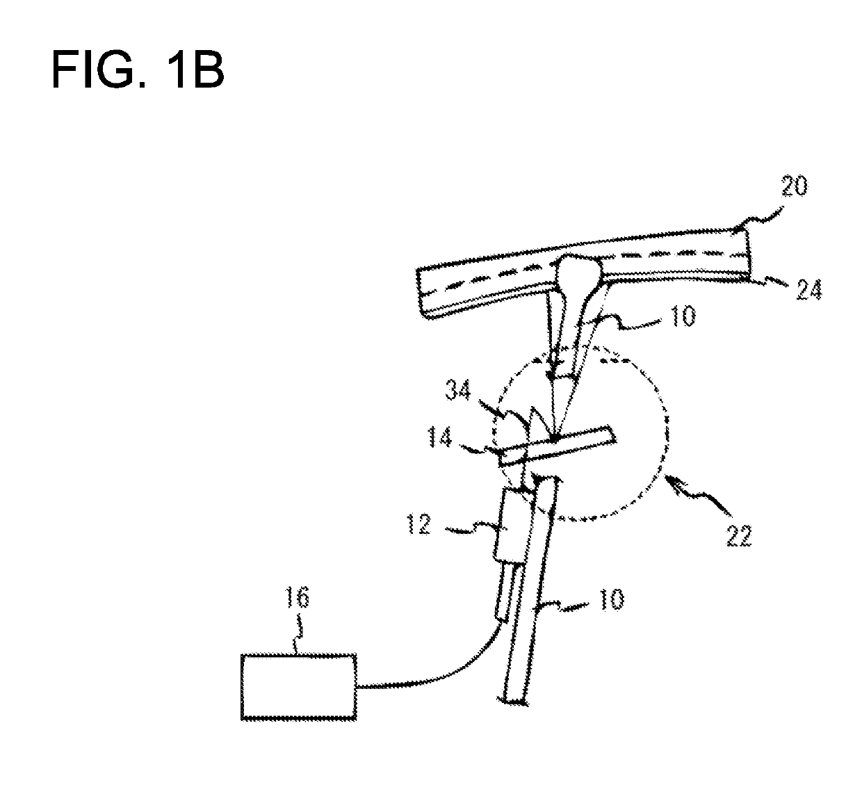
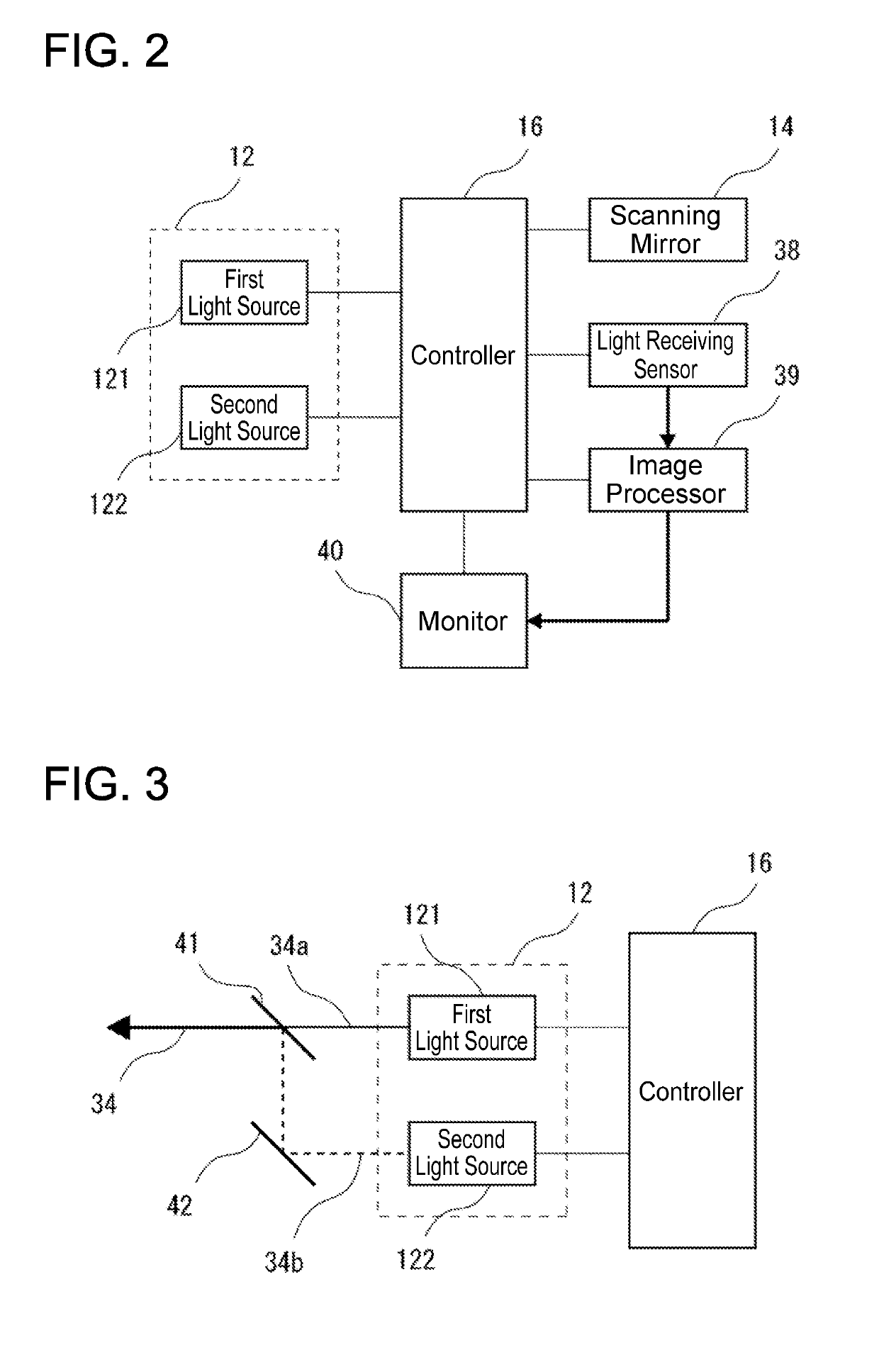
[0022]Hereinafter, a scanning laser ophthalmoscope according to an embodiment will be described. As shown in FIGS. 1A and 1B, a temple 10 of eyewear that holds a guide mirror 24 and an eyewear lens 20 is provided with a light source 12 configured to emit laser light 34 and a scanning mirror 14 which is a scanner configured to scan the laser light 34 emitted from the light source 12 in a two-dimensional direction. An infrared light transmission filter 37, a light receiving sensor 38, and an image processor 39 are provided at an external device (not shown) which is separated from the temple 10 (i.e., the eyewear). The light source 12 is configured to emit a plurality of laser light with different wavelengths. In FIG. 1B, the illustration of the laser light 34 is partly omitted for clarity of the figure.

[0023]A controller 16 is configured to control the emission of the laser light 34 from the light source 12. The controller 16 may be provided on the temple 10 of the eyewear similarly t...


PUM


Abstract

A scanning laser ophthalmoscope may include: a light source configured to emit laser light; a scanner configured to scan the laser light emitted from the light source two-dimensionally; a guide mirror configured to guide the laser light scanned by the scanner to a fundus of an eye of a subject; a guide mirror holder configured to hold the guide mirror in a predetermined positional relationship with the eye of the subject; a light receiver configured to receive reflected light of the laser light reflected on the fundus; and an image generator configured to generate a fundus image based on the reflected light received by the light receiver. The guide mirror may be disposed on a path connecting the scanner and the fundus of the eye of the subject, and disposed in front of the eye of the subject. The scanner may be disposed at the guide mirror holder.

Description

TECHNICAL FIELD[0001]The technique disclosed herein relates to a scanning laser ophthalmoscope (SLO) configured to capture a frontal image of an eye of a subject.BACKGROUND ART[0002]In the field of ophthalmology, a scanning laser ophthalmoscope is known which obtains a fundus image by scanning laser light on a fundus of an eye of a subject in a two-dimensional direction (for example, Japanese Patent Application Publication No. H11-197109).SUMMARY[0003]Many ophthalmologic devices, including such an ophthalmoscope as above, are provided with a means for contacting a head of a subject to hold an eye of the subject at a predetermined position with respect to an optical system for ocular examination or image capturing.[0004]However, since the above-mentioned contacting means is not configured to completely fix the head of the subject with respect to the device, the eye of the subject (the head of the subject) may move during the ocular examination or image capturing. In this case, the oc...

Claims


Application Information

Patent Timeline
IPC IPC(8): A61B3/12A61B3/10A61B3/00
CPCA61B3/0091A61B3/1025A61B3/1225A61B3/10
Inventor SUGAWARA, MITSURUSUZUKI, MAKOTOMUKAI, HIDEO
Owner LASER
Why Eureka
Try Eureka