Dispenser for discharging liquids, and operating method therefor

a technology for discharging liquids and operating methods, which is applied in the direction of instruments, single-unit apparatuses, volume meters, etc., to achieve the effect of preventing the complete separation of chamber components and high stability

Active Publication Date: 2019-09-12
APTAR RADOLFZELL
View PDF5 Cites 3 Cited by
  • Summary
  • Abstract
  • Description
  • Claims
  • Application Information

AI Technical Summary

Benefits of technology

[0064]Besides the design described above while utilizing the cover as a safeguard, a design in which the chamber components comprise in each case one cylindrical external portion, wherein the two external portions are push-fitted into one another in an overlapping manner has been demonstrated so as to be advantageous in constructive terms. A particularly high level of stability is achieved on account thereof. The overlapping regions of preferably a few millimeters of overlapping length are moreover very suitable for the disposal of latching elements for latching the chamber components.
[0065]It is furthermore advantageous when a basic housing of the discharge head surrounds one of the external portions mentioned in such a manner that a widening of the external portion is delimited so as to counteract any separation of the chamber components. The complete separation of the chamber components can thus be prevented. A leakage is indeed possible, but a potentially complete separation of the chamber components that could cause injury is effectively prevented.

Problems solved by technology

However, in the case of such a design in which the actuation handle is to switch the intermediate valve and the infeed valve it is necessary for the respective actuation portion for switching the infeed valve is repositionable in relation to the chamber unit, this being associated with the problem described of the sliding seal required there in this instance.

Method used


Image

  • Dispenser for discharging liquids, and operating method therefor
  • Dispenser for discharging liquids, and operating method therefor
  • Dispenser for discharging liquids, and operating method therefor

Examples


Embodiment Construction

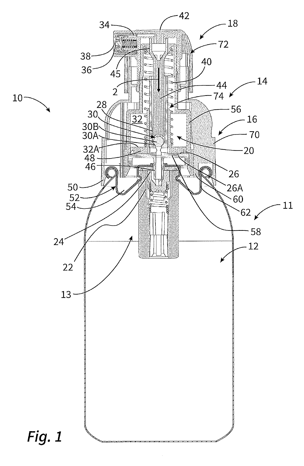
[0081]FIG. 1 shows a liquid dispenser 10 in a sectional overall illustration.

[0082]The liquid dispenser 10 includes a storage unit 11 which comprises a liquid reservoir 12 having a discharge valve assembly 13. A discharge head 14 is placed on the storage unit 11 and by means of a fastening device 50 is connected in a latching manner to the storage unit 11. Said discharge head 14 in turn includes an adapter unit 16 and a discharge unit 18. A discharge opening 38 is provided on this discharge unit 18.

[0083]The discharge head 14 contains the predominant numbers of components of a metering device 20. Said metering device 20 includes a pre-metering chamber 26, which in the state of FIG. 1 is reduced to the maximum, and a main metering chamber 32. The pre-metering chamber 26 and the main metering chamber 32 are provided in a chamber unit 74 which inter alia makes available an external wall 56 and an end wall 58 as external walls of the chamber unit 74. The pre-metering chamber 26 and the ...


PUM


Abstract

Dispenser with a reservoir for storing liquid, and a discharge opening through which the liquid can be dispensed. The dispenser includes a metering device for discharging a defined liquid quantity upon actuation of the dispenser. The metering device at the entry side is connected to the reservoir and at the exit side is connected to the discharge opening. The metering device includes a pre-metering chamber which via an infeed duct is connected to the reservoir, and a main metering chamber which via an intermediate duct is connected to the pre-metering chamber, and via a discharge duct is connected to the discharge opening. The pre-metering chamber and the main metering chamber each have one repositionable wall, the respective chamber volume being variable by repositioning the wall. The walls are operatively coupled such that a volumetric enlargement of the pre-metering chamber causes a volumetric reduction of the main metering chamber.

Description

CROSS-REFERENCE TO RELATED APPLICATIONS[0001]This claims priority from European Application No. 18161056.9, filed Mar. 9, 2018, the disclosure of which is hereby incorporated by reference in its entirety.FIELD OF APPLICATION AND PRIOR ART[0002]Dispensers for liquids are known from various sectors in the prior art. Such dispensers have a liquid reservoir within which a liquid is stored prior to discharging, and a discharge opening through which the liquid can be dispensed. Generic dispensers furthermore have a metering device which permits an approximately consistent liquid quantity to be discharged at all times by way of an actuation movement.[0003]A liquid in the context of the invention are understood to be liquids having a comparatively low viscosity, similar to that of water, as well as cream-type or gel-type liquids having a comparatively high viscosity.[0004]Generic liquid dispensers as well as liquid dispensers according to the invention can be used for discharging pharmaceut...

Claims


Application Information

Patent Timeline
Patent Type & Authority Applications(United States)
IPC IPC(8): B05B11/00B65D83/54
CPCB05B11/3001B65D83/54B05B12/085B05B11/1042B05B11/109B65D83/546G01F11/025G01F11/028B05B11/1001
Inventor SCHMID, FELIX
Owner APTAR RADOLFZELL
Why Eureka
Try Eureka