Eureka AIR delivers breakthrough ideas for toughest innovation challenges, trusted by R&D personnel around the world.

Power coated fdm printed item, related manufacturing method and apparatus

Pending Publication Date: 2019-09-12
SIGNIFY HLDG BV
View PDF0 Cites 3 Cited by
  • Summary
  • Abstract
  • Description
  • Claims
  • Application Information

AI Technical Summary

Benefits of technology

The patent text explains about FDM printers and the use of different substrates such as metallic and glass surfaces for printing 3D objects. The text also highlights the development of LED luminaires and lighting solutions using FDM printing. The text discusses the use of post additives to prevent powder caking and extenders to reduce glossiness and provide extra durability to the coating. The technical effects of the patent text involve the use of FDM printing for fast, low-cost, and complex 3D printing, which can be utilized for various applications such as LED luminaire production.

Problems solved by technology

While this technique produces smooth surfaces the photo curable materials are not very stable and they also have relatively low thermal conductivity to be useful for injection molding applications.

Method used


Image

  • Power coated fdm printed item, related manufacturing method and apparatus
  • Power coated fdm printed item, related manufacturing method and apparatus
  • Power coated fdm printed item, related manufacturing method and apparatus

Examples


examples

[0092]For powder coating we used prints which were either made using an electrically conductive filament or made using a non-conducting filament which were subsequently provided with an electrically conductive layer. The samples were then coated by a powder obtained from various suppliers using corona discharge method. The powder coated samples were the placed in a preheated oven at a desired temperature for a length of time to obtain a layer of cross-linked polymer. Powders based on epoxy, polyurethane, and polyesters and their mixtures, were used.

[0093]Best results were obtained for a very smooth surface when powders were used which could flow well during the melting / reaction. These powders were either pure resin or they contained nano sized pigments such as TiO2 and carbon. These coating showed good filling of ripples (“stair step”) and gave glossy smooth surfaces. Coatings which are so called structured coatings did not show high flow and therefore they could not fully cover rip...


PUM

PropertyMeasurementUnit
Surface resistivityaaaaaaaaaa
Temperatureaaaaaaaaaa
Electrical conductivityaaaaaaaaaa

Abstract

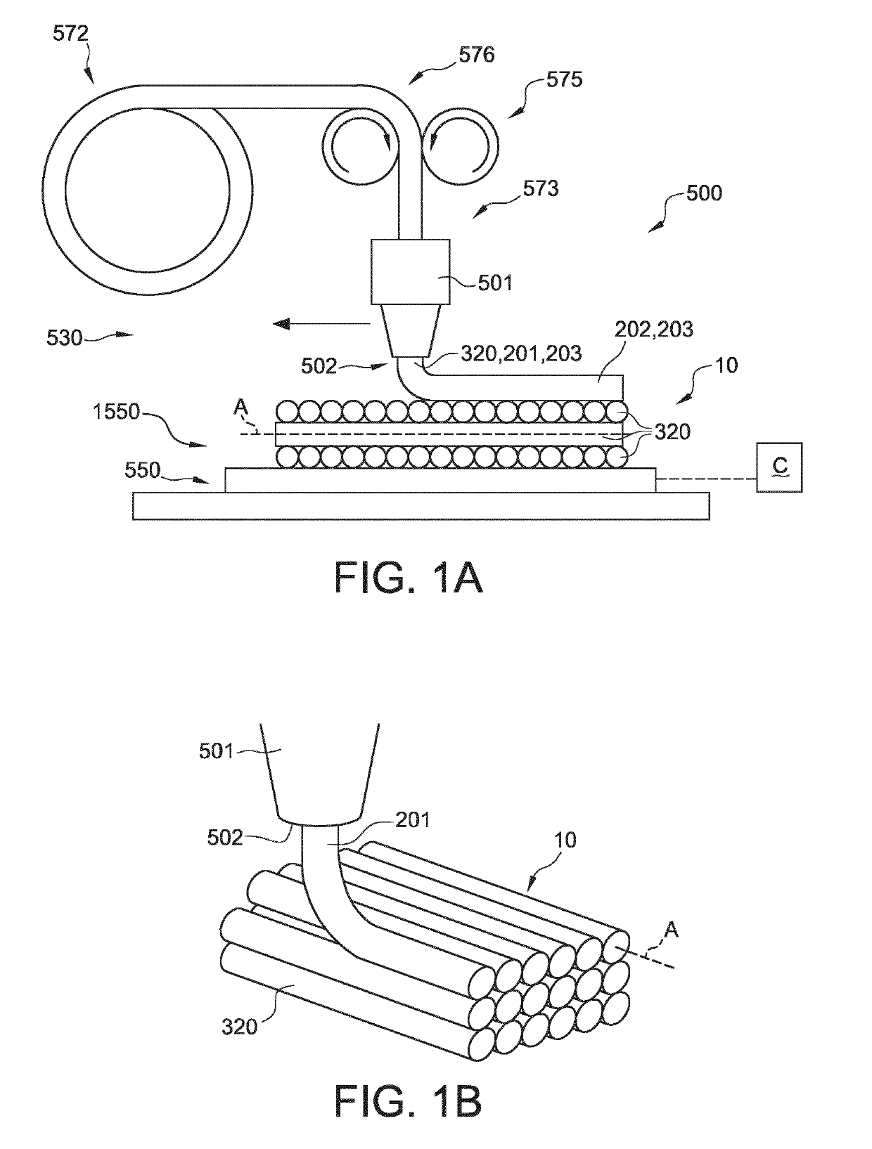
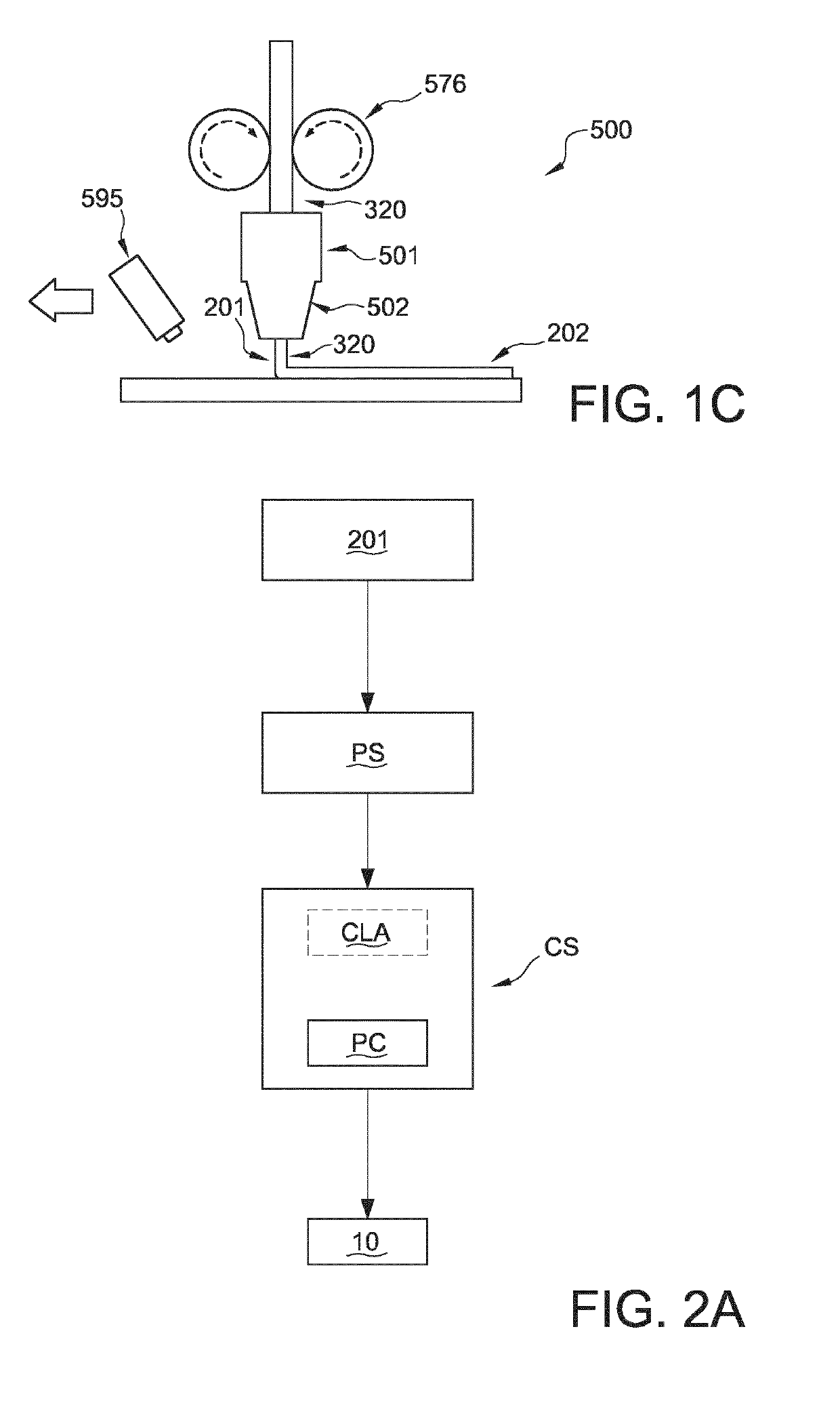
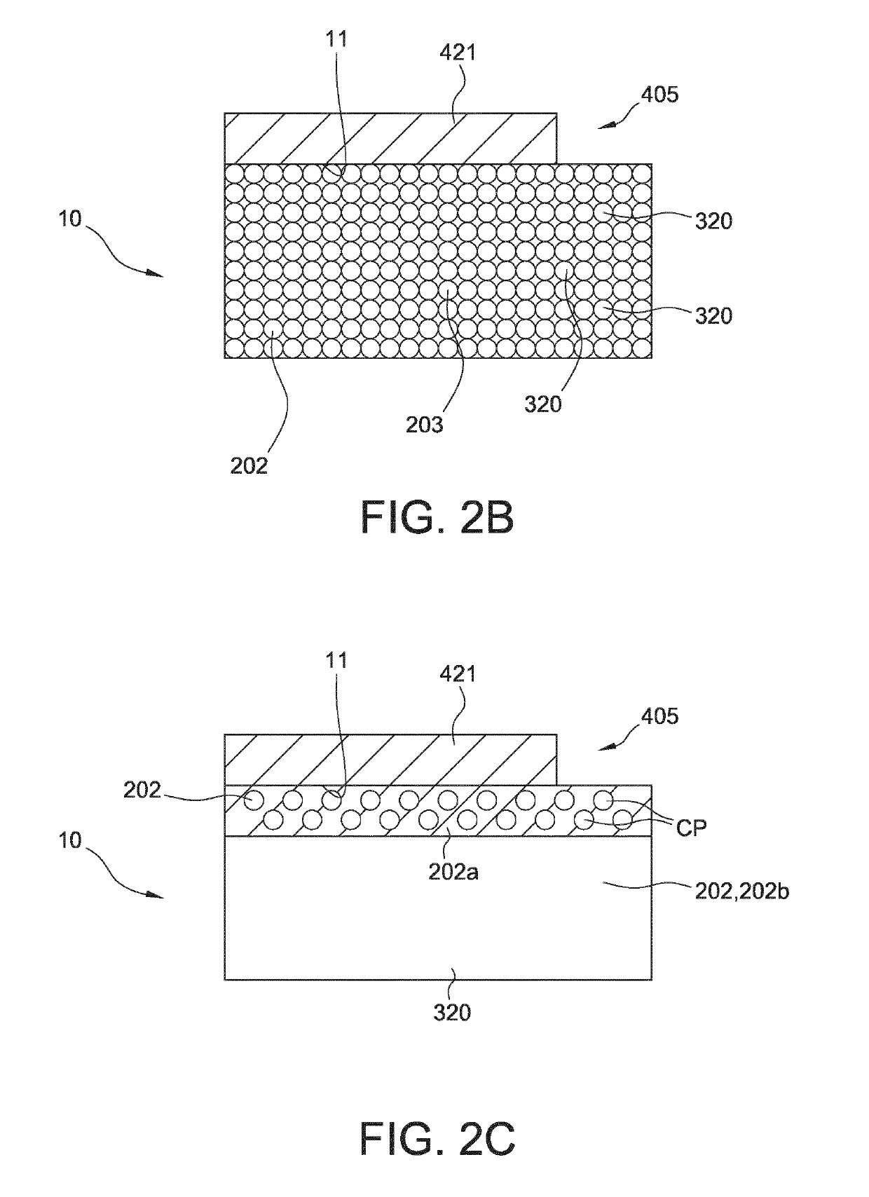
The invention provides a method for 3D printing a 3D item, the method comprising providing 3D printable material (201) and printing during a printing stage said 3D printable material (201), wherein the 3D printable material (201) comprises a thermoplastic material, to provide said 3D item, wherein the 3D item comprises an item surface, wherein the method further comprises providing a powder coating with a powder coating device (595) on at least part of said item surface during a coating stage. The invention also relates to the item manufactured by such method and to the manufacturing apparatus (500) used.

Description

FIELD OF THE INVENTION[0001]The invention relates to a method for manufacturing a 3D item by means of fused deposition modeling. The invention also relates to the 3D (printed) item obtainable with said method. Further, the invention relates to an optical element including such 3D (printed) item. Yet further, the invention also relates to a 3D printer for printing such 3D item with such method.BACKGROUND OF THE INVENTION[0002]Smoothing methods for layered deposition modeling surfaces are known in the art. U.S. Pat. No. 8,123,999 B2, for instance, describes a method for making a three-dimensional object comprising the steps of: (i) providing an object built from a modeling material using a fused deposition modeling technique, wherein the modeling material comprises a thermoplastic resin, wherein the built object has an object surface formed of the modeling material, the object surface having at least one surface effect due to the fused deposition modeling technique that extends substa...

Claims


Application Information

Patent Timeline
IPC IPC(8): B29C64/118B33Y10/00B33Y30/00B29C64/209B29C64/30B33Y40/00
CPCB33Y40/00B29C64/118B29C64/30B33Y30/00B29C64/209B29K2101/12B33Y70/00B33Y10/00B29L2011/00B33Y80/00B29C70/64B29C70/882
Inventor HIKMET, RIFAT ATA MUSTAFAANSEMS, WILHELMUS JOHANNES HENDRICUS
Owner SIGNIFY HLDG BV
Why Eureka
Eureka Blog
Learn More