Eureka AIR delivers breakthrough ideas for toughest innovation challenges, trusted by R&D personnel around the world.

Image forming method and image forming apparatus

Inactive Publication Date: 2005-03-17
FUJIFILM HLDG CORP
View PDF2 Cites 2 Cited by
  • Summary
  • Abstract
  • Description
  • Claims
  • Application Information

AI Technical Summary

Benefits of technology

[0006] The methods disclosed in JP 10-319621 A, JP 2001-92171 A, and JP 2000-264481 A are capable of adding enhanced value to images by providing image surfaces with gloss like that of photographic prints or by reducing glossiness of image surfaces to improve viewability.
[0010] The present invention has been made to solve the problems of the conventional techniques, and an object of the present invention is to provide an image forming method and an image forming apparatus capable of highly freely providing suitable glossiness in accordance with the contents of an image, e.g. objects recorded in the image, and more preferably, capable of providing glossiness appropriate for different contents recorded in different areas of the image, so as to form a high-quality image that properly expresses texture.
[0023] According to the image forming method and the image forming apparatus of the present invention, it is possible to highly freely provide suitable glossiness in accordance with the contents of image areas, like objects recorded in the image, and more preferably, to provide different degrees of glossiness appropriate for the contents in different areas of the image, so as to form a high-quality image (hard copy) that properly expresses texture.

Problems solved by technology

However, the methods disclosed in the patent documents cited above do not allow high degree of freedom to select the degree of glossiness, so they often fail to provide glossiness suitable for the image.
Moreover, the methods disclosed in JP 10-319621 A, JP 2001-92171 A, and JP 2000-264481 are only capable of providing uniform glossiness on the entire image surface but are incapable of providing different degrees of glossiness in accordance with the contents recorded in different areas of the image.
However, the conventional techniques are incapable of such glossiness control.

Method used


Image

  • Image forming method and image forming apparatus
  • Image forming method and image forming apparatus
  • Image forming method and image forming apparatus

Examples


Embodiment Construction

[0031] The image forming method of the present invention is now described in detail referring to the preferred embodiment illustrated in the accompanying drawings.

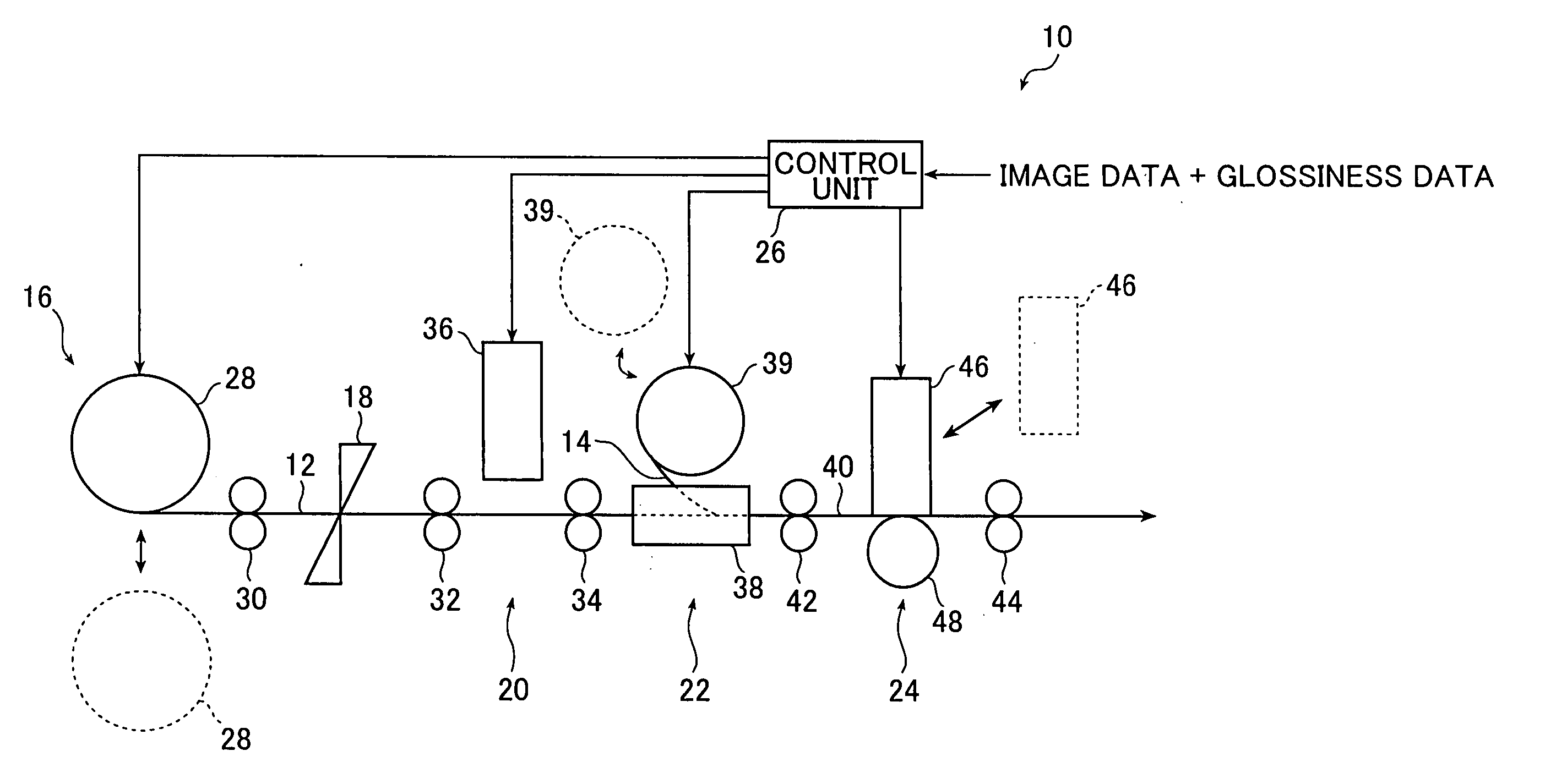
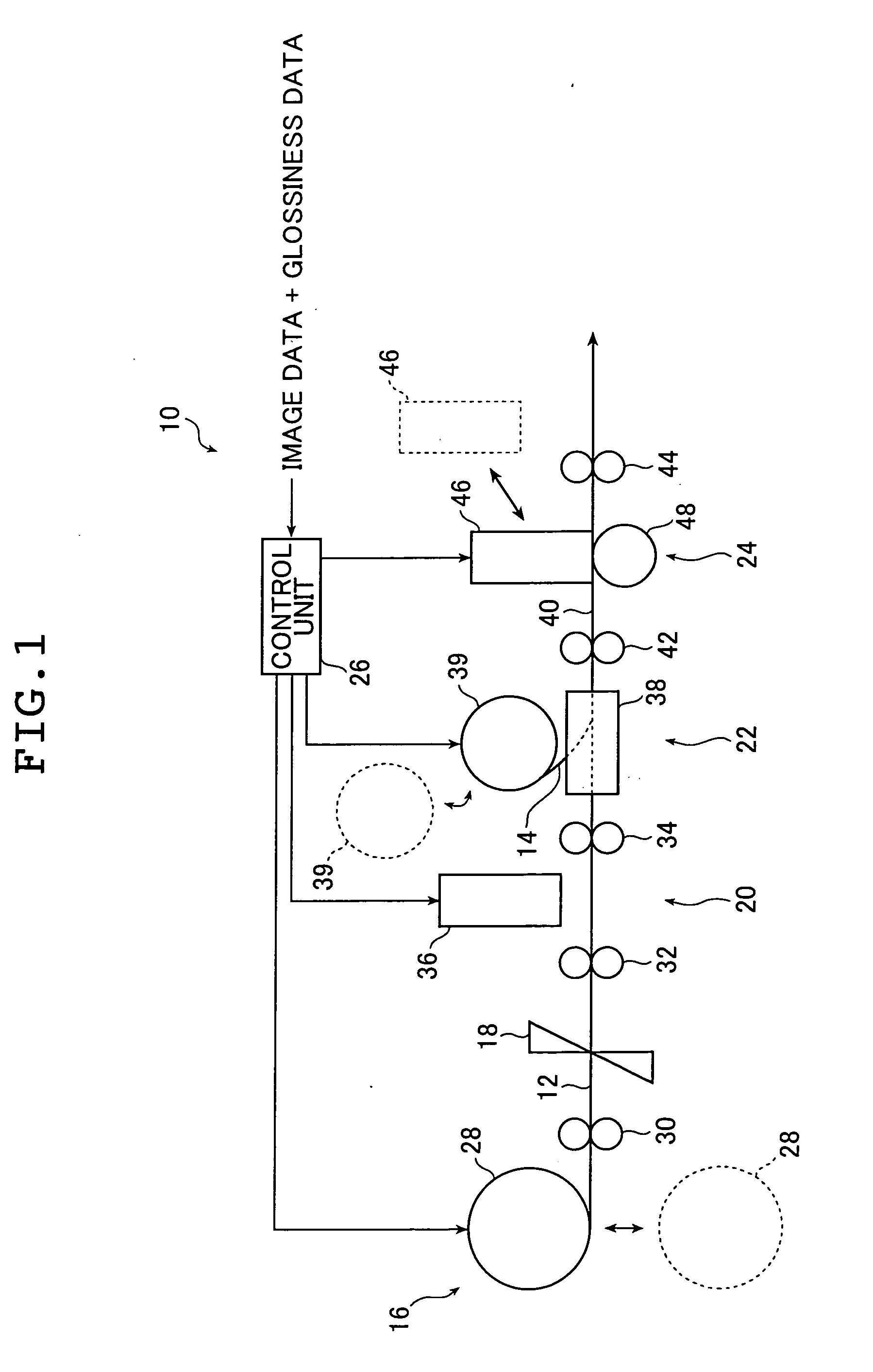
[0032]FIG. 1 is a conceptual diagram illustrating an image forming apparatus that implements an example of the image forming method of the present invention.

[0033] An image forming apparatus 10 of FIG. 1 records an image by ink jet on the surface (on an image recording layer) of an image recording medium 12 (hereinafter referred to as recording medium 12), laminates a coating film 14 on the image recording surface, and then processes the surface of the coating film 14. The image forming apparatus 10 basically includes a medium feeding unit 16, a cutter 18, an image recording unit 20, a coating film laminating unit 22, a surface processing unit 24, and a control unit 26. Though not shown in FIG. 1, the image forming apparatus 10 may further include any components that would be provided in image forming apparatuses using s...


PUM


Abstract

The image forming method includes a recording step of recording an image on an image recording layer of an image recording medium according to image data, a material setting step of setting a coating film to be provided on the image recording layer according to glossiness data indicating glossiness of the image reproduced by the image data, a condition setting step of determining a condition of a surface processing of the coating film by considering the set coating film and according to the glossiness data, and a processing step of performing the surface processing of the coating film in accordance with the determined surface processing condition.

Description

BACKGROUND OF THE INVENTION [0001] The present invention relates to a technical field of image formation, and more particularly to an image forming method and an image forming apparatus capable of forming a high-quality image provided with gloss appropriate for the contents etc. of the image. [0002] Various surface processing techniques are known for finishing image surfaces glossy like those of photographic prints or properly controlling surface glossiness so that images look fine, So as to add enhanced value to Images (hard copies) outputted by ink jet printers and electrophotographic printers. [0003] For example, JP 10-319621 A discloses a method of forming an image by electrophotography, in which, after formation of a color image, a transparent layer of inorganic oxide fine particles with a refractive index of 1.4 to 1.6 and water-soluble resin is formed so that the refractive index of the toner used to form the image, the refractive index of the inorganic oxide fine particles, ...

Claims


Application Information

Patent Timeline
IPC IPC(8): G01D11/00G03B21/18
CPCG03B21/18
Inventor KUSUNOKI, NAOKI
Owner FUJIFILM HLDG CORP
Why Eureka
Eureka Blog
Learn More