Composite Structure Splice and Method

a composite structure and splicing technology, applied in the direction of fuselages, transportation and packaging, other domestic objects, etc., can solve the problems of large space occupation, labor-intensive process, and inability to fabricate these stiffeners using automated equipment, so as to reduce the amount of stress and reduce the undesired wrinkles of the composite structure

Pending Publication Date: 2019-09-12
THE BOEING CO
View PDF3 Cites 1 Cited by
  • Summary
  • Abstract
  • Description
  • Claims
  • Application Information

AI Technical Summary

Benefits of technology

[0011]Yet a further embodiment of the present disclosure provides a composite structure comprising a first section and a second section for the composite structure. The first section has a first end with a chevron shape chevron shape comprised of a group of chevrons and in which first composite layers in the first section have a first step pattern at the first end. A second section for the composite structure is formed in which the second section has a second end with a counterpart shape to the chevron shape in which the first section and the second section have a desired cross-sectional shape, an

Problems solved by technology

Further, the complex geometries include stiffeners with bends, twists, and joggles within the interior of the fuselage.
As a result, challeng

Method used


Image

  • Composite Structure Splice and Method
  • Composite Structure Splice and Method
  • Composite Structure Splice and Method

Examples


Embodiment Construction

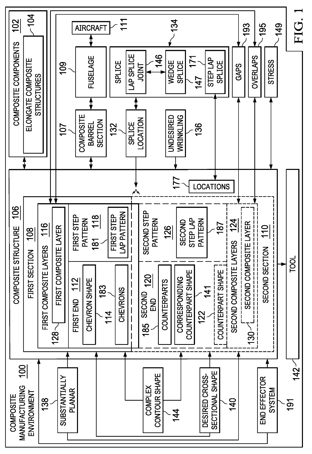
[0039]The illustrative embodiments recognize and take into account one or more different considerations. For example, the illustrative embodiments recognize and take into account that laying up composite materials in three-dimensional shapes to form composite structures can be more complex and time-consuming than desired. The illustrative embodiments also recognize and take into account that fabricating composite structures such as stringers with at least one of contours or twists can be performed in a semi-automated fashion. The equipment utilized, however, involves unique or custom tooling for the desired geometries.

[0040]Further, the illustrative embodiments recognize and take into account that splicing techniques can be utilized for stiffeners with perpendicular cuts. The illustrative embodiments recognize and take into account that this type of splicing may reduce some amount of wrinkling but does not fully address the occurrence of undesired inconsistencies such as wrinkling. ...


PUM

PropertyMeasurementUnit
Structureaaaaaaaaaa
Shapeaaaaaaaaaa
Stress optical coefficientaaaaaaaaaa

Abstract

A method for fabricating a composite structure. A first section for the composite structure is formed in which the first section has a first end with a chevron shape, wherein first composite layers in the first section has a first step pattern at the first end. A second section for the composite structure is formed in which the second section has a second end with a counterpart shape to the chevron shape and in which second composite layers in the second section have a second step pattern at the second end. The first end the second end are positioned such that a first composite layer in the first composite layers in the first step pattern overlap the second composite layers in the second step pattern at a splice location.

Description

BACKGROUND INFORMATION1. Field[0001]The present disclosure relates generally to fabricating composite structures and, in particular, to fabricating composite structures with splices.2. Background[0002]Composite fuselages contain complex geometries. Portions of the fuselage have a constant diameter. The nose and tail portions of the fuselage have diameters that taper. Further, the complex geometries include stiffeners with bends, twists, and joggles within the interior of the fuselage. As a result, challenges are present in fabricating these stiffeners using automated equipment. The challenges include reducing undesired inconsistencies such as wrinkling, ply bridging, or other undesired inconsistencies.[0003]For example, high contour fabrication can be performed through layer by layer hand draping layers on a tool. This process is labor-intensive and utilizes large amounts of space.[0004]Therefore, it would be desirable to have a method and apparatus that take into account at least s...

Claims


Application Information

Patent Timeline
IPC IPC(8): B29C70/34
CPCB29C70/34B29K2105/0881B29L2031/3076B29K2105/089F16S3/04B64C1/064B29D99/0003B29C66/72141B29C66/12821B29C66/12842B29C66/721B29K2105/0872B29C66/73921B29C66/73941B29L2031/003B29L2031/008Y02T50/40B29C70/304
Inventor KENDALL, JAMES R.SURIYAARACHCHI, RAVIENDRA SIDATHSHAW, PAUL D.
Owner THE BOEING CO
Why Eureka
Try Eureka