Vehicle rear structure

a rear structure and vehicle technology, applied in the field of vehicle rear structure, can solve the problems that the conventional vehicle rear structure may not efficiently absorb collision energy, and achieve the effect of efficient absorption of collision energy

Active Publication Date: 2019-09-12
HONDA MOTOR CO LTD
View PDF6 Cites 7 Cited by
  • Summary
  • Abstract
  • Description
  • Claims
  • Application Information

AI Technical Summary

Benefits of technology

[0008]According to the vehicle rear structure of the present invention, it is possible to efficiently absorb collision energy even when a collision load is disproportionately inputted to one of the rear side frames.

Problems solved by technology

If the rear side frame on the one side is solely deformed as a consequence of the disproportionate input of the collision load as mentioned above, the conventional vehicle rear structure may fail to efficiently absorb the collision energy.

Method used


Image

  • Vehicle rear structure
  • Vehicle rear structure
  • Vehicle rear structure

Examples


Embodiment Construction

[0014]A vehicle rear structure according to an embodiment to carry out the present invention (this embodiment) will be described in detail with reference to the drawings as appropriate. In the following, the present invention will be described in concrete terms based on an example of a vehicle rear structure to be applied to a plug-in hybrid automobile, for instance, which mounts a battery for a drive train.

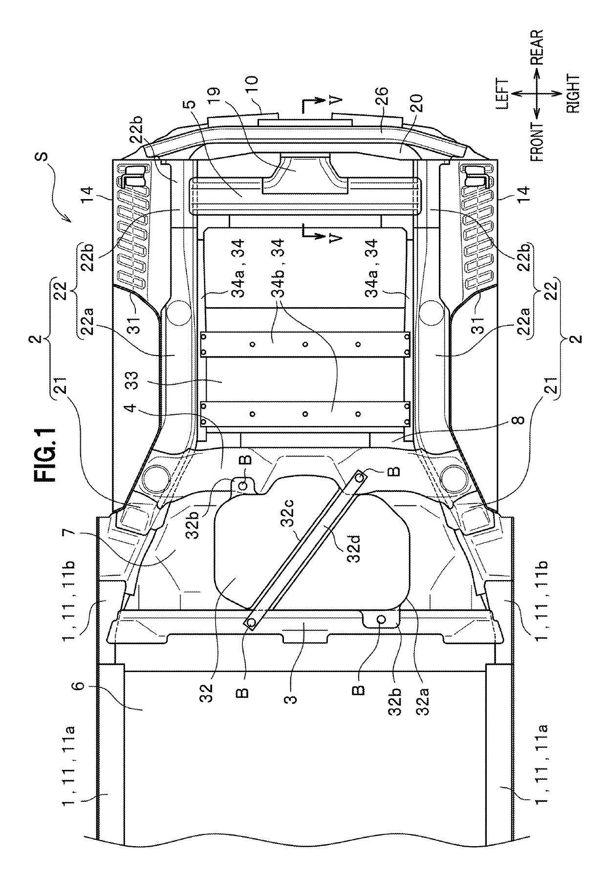
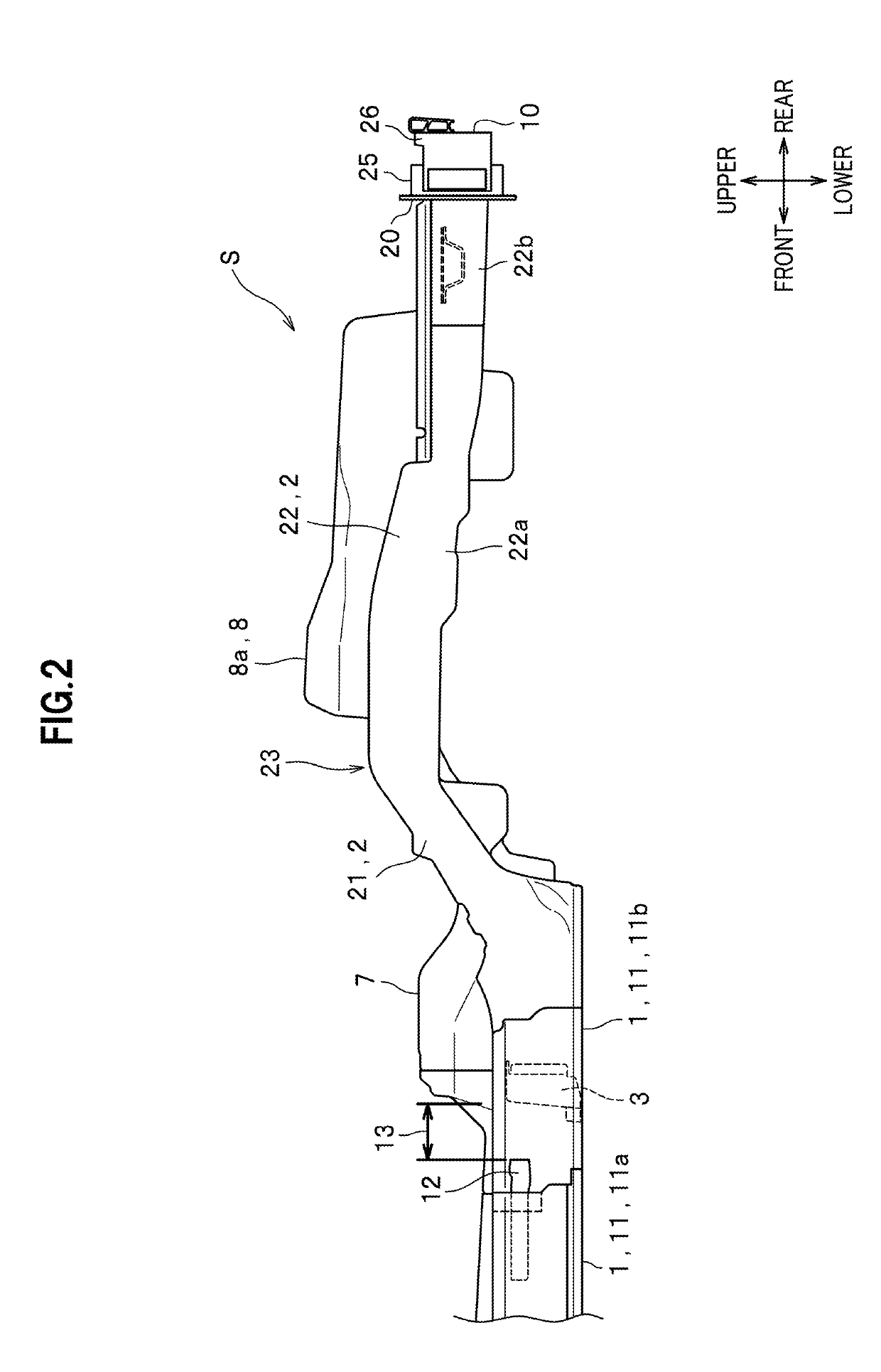
[0015]FIG. 1 is a bottom view of a vehicle body 10 including a vehicle rear structure S of this embodiment and FIG. 2 is a left side view thereof. In the following description, upper, lower, front, rear, left, and right directions coincide with upper, lower, front, rear, left, and right directions viewed from a driver seated in a vehicle. Here, a right-left direction coincides with a vehicle width direction.

[0016]As shown in FIG. 1, the vehicle rear structure S of this embodiment includes: side sills 1 located on two sides of the vehicle body 10 and extending in a front-back dire...


PUM


Abstract

A vehicle rear structure includes a pair of rear side frames provided on right and left sides at a rear part of a vehicle body, and an on-board component disposed between the rear side frames. Each rear side frame includes a protecting part arranged side by side with the on-board component in a vehicle width direction, and a rear extending part extending rearward from the on-board component. A cross member is provided to connect the rear extending parts to each other at positions each located away from a front end and a rear end of the corresponding rear extending part.

Description

BACKGROUND OF THE INVENTION1. Field of the Invention[0001]The present invention relates to a vehicle rear structure.2. Description of the Related Art[0002]There has been known a conventional vehicle rear structure in which a battery for driving a vehicle is disposed between rear side frames that are arranged on two sides at a rear part of a vehicle body (see Japanese Patent Application Publication No. 2016-196207 or Patent Literature 1, for example). A reinforcement member is disposed along a front-rear direction (a longitudinal direction) in each rear side frame of this vehicle rear structure. A rear end of the reinforcement member extending in the rear side frame stops extending at a position corresponding to a rear end of the battery. In other words, due to the reinforcement member, a front part of this rear side frame located in front of the rear end position of the battery has a larger strength than that of a rear part of the rear side frame behind the rear end position of the ...

Claims


Application Information

Patent Timeline
Patent Type & Authority Applications(United States)
IPC IPC(8): B62D25/20B60K1/04
CPCB60K1/04B62D25/2027B60K2001/0416B62D25/2036B60Y2306/01B60K15/063B60K2015/0638B62D21/02B62D21/15B62D21/152B62D25/087
Inventor TATSUWAKI, MASAAKIHARADA, JUNYAKUMAGAI, SHINJI
Owner HONDA MOTOR CO LTD
Why Eureka
Try Eureka