
Body frame structure for a vehicle and method for manufacturing thereof

a body frame and vehicle technology, applied in the direction of roofs, transportation and packaging, vehicle arrangements, etc., can solve the problems of complicated construction, and achieve the effect of simple structure and effective absorption of collision energy

Inactive Publication Date: 2004-05-18
MAZDA MOTOR CORP
View PDF28 Cites 41 Cited by
  • Summary
  • Abstract
  • Description
  • Claims
  • Application Information

AI Technical Summary

Benefits of technology

In view of the aspect above, the first object of the present invention is to provide a body frame structure which induces larger initial load in a collision and induces the bending deformation in the frame thereafter for effectively absorbing the collision energy with a simple structure. The second object of the present invention is to provide a manufacturing method of the body frame used for achieving the object above.
Accordingly, because the brittle section is approximately equal to the other sections in axial compressive strength, the brittle section will not easily buckle, so as to induce larger collision reaction. Thereafter, the body frame will buckle at the brittle section and bend to effectively absorb the collision energy.
Preferably, the peripheral section and the peripheral section of the brittle section may be hardened by a hardening treatment. Accordingly, the boundaries between the brittle sections and the other sections are prevented from being unexpectedly and locally weakened, so as to reliably induce the buckling at the brittle section.
It is further preferred that the hardening be achieved by a heat treatment. Accordingly, the hardening treatment can be easily achieved by a conventional process.
Moreover, the brittle section may be formed on a planar surface of the body frame. Accordingly, more freedom is available for the location of the brittle section, and the brittle section is easily formed on a planar surface of the body frame because the body frame generally includes a planar surface elongated in a lengthwise direction.
Still further, it is preferred that the body frame include a predetermined member with the predetermined cross-section formed from at least one sheet metal and the brittle section be simultaneously formed during forming the sheet metal into the predetermined member. Accordingly, the body frame with the brittle section is manufactured by effectively utilizing the existing manufacturing processes.

Problems solved by technology

In the frame structure disclosed in Japanese Patent Publication No. 2000-53022, however, the beams are required for triggering the bending deformation of the frame, which complicates the construction.

Method used


Image

  • Body frame structure for a vehicle and method for manufacturing thereof
  • Body frame structure for a vehicle and method for manufacturing thereof
  • Body frame structure for a vehicle and method for manufacturing thereof

Examples


Embodiment Construction

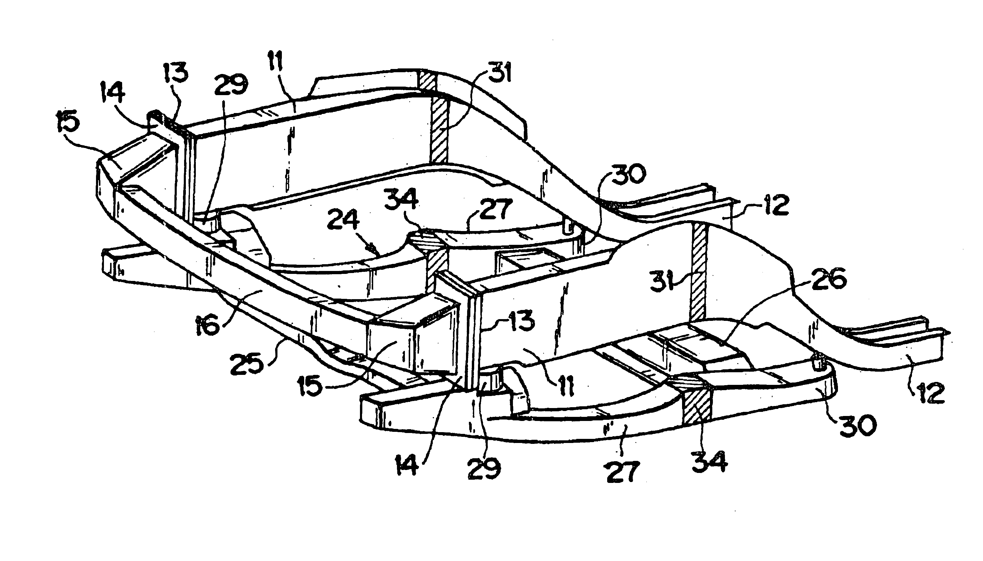
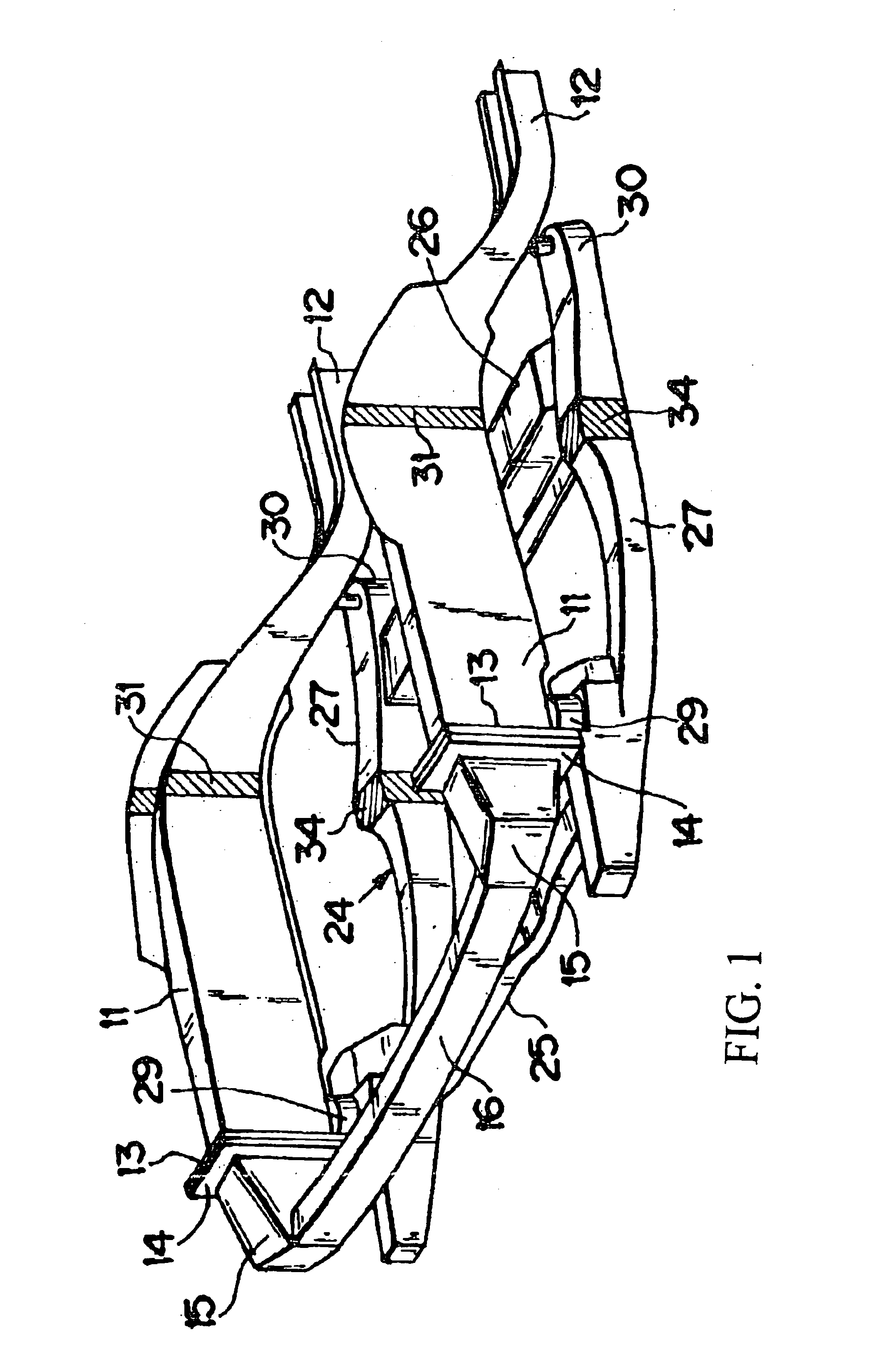
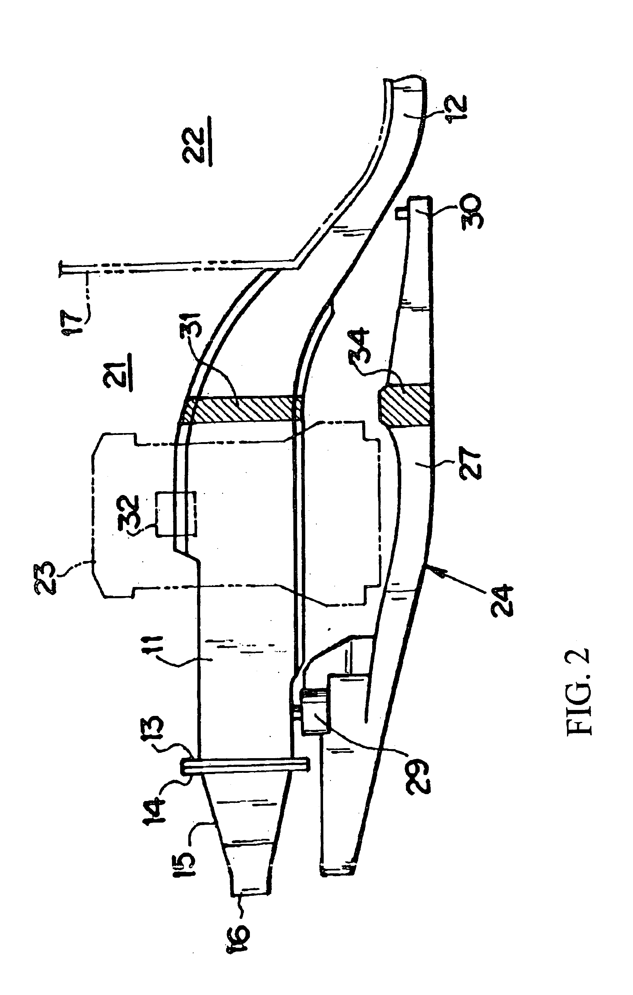
Referring to FIG. 1 to FIG. 3 illustrating a front body structure, identified by 11 is a pair of the left and right front frames (or front side frame) extending in vehicular longitudinal direction and unitarily formed with floor flames 12 at their rear ends.

The front ends of the pair of the left and right front frames 11 are provided with joint flanges 13, respectively. The joint flanges 13 are joined to joint flanges 14 unitarily formed with joint members 15. The left and right joint members 15 are connected to each other by a bumper reinforcement 16 extending laterally.

As shown in FIG. 2, above and rearward of the front frames 11, a dash lower panel 17 is disposed which separates an engine compartment 21 in front and a passenger compartment 22 behind.

The pair of the left and right front frames 11 extend approximately straight from their front ends to a section proximate to the dash lower panel 17, and gradually bend downwardly rearward from the section proximate to the dash panel ...


PUM


Abstract

A pair of left and right front frames are formed with brittle sections on proximal portions of the frames, by the provision of the smaller cross-sectional area than other sections of the frame. The brittle sections and their peripheral sections are processed so as to become approximately equal to the other sections of the front frames in axial compressive strength by way of a hardening treatment like quenching. In an early-phase of a collision, the hardened brittle sections will not buckle so as to induce larger initial load. Thereafter, the brittle sections will buckle because of their lower ductility, so that the front frames begin bending deformation to effectively absorb the collision energy.

Description

BACKGROUND OF THE INVENTION1. Field of the InventionThe present invention relates to a body frame structure for a vehicle which induces larger initial load in a collision and induces the bending deformation in the frame thereafter for effectively absorbing the collision energy with a simple structure and a method for manufacturing thereof.2. Description of the Related ArtBody frames serving as automotive structural members are indispensably required to not only be excellent in stiffness, but also effective in absorption of energy during an automobile collision. To cope with a frontal collision as a typical example of an automotive collision, an approach to energy absorption has been often attempted which uses a pair of left and right front frames located in front of a passenger compartment and extending in the vehicular longitudinal direction, with axial (or lengthwise) stiffness gradually decreased from a rear section (or passenger-compartment side) towards a frontal section. Thus,...

Claims


Application Information

Patent Timeline
Patent Type & Authority Patents(United States)
IPC IPC(8): B62D21/15B62D21/00B62D25/08B62D25/20
CPCB62D21/152B62D21/155B62D29/007
Inventor HANAKAWA, KATSUNORIISHIDA, KYOSOSUNAKAWA, TAKAYUKISUGIMOTO, YUKIHIRO
Owner MAZDA MOTOR CORP
Learn More