Bi-directional fixating/locking transvertebral body screw/intervertebral cage stand-alone constructs

a transvertebral body screw and intervertebral cage technology, applied in the field of unique universal bidirectional screw (bds) system, can solve the problems of never being less compatible, achieve the effect of enhancing the integrity and strength of the cage itself, reducing the possibility of the cage breaking or cracking, and increasing the strength of the screw engagemen

Active Publication Date: 2019-09-19
MOSKOWITZ FAMILY LLC
View PDF8 Cites 0 Cited by
  • Summary
  • Abstract
  • Description
  • Claims
  • Application Information

AI Technical Summary

Benefits of technology

[0010]Herein described are a plurality of device embodiments which combine in a single stand-alone construct the dual functions of: a) an intervertebral cage spacer which can be filled with bone fusion material maintaining disc height, and, b) a bi-directional fixating / fusion transvertebral body screw apparatus. These embodiments are described for posterior and anterior lumbar (and anterio-lateral thoracic) intervertebral placement, and anterior cervical intervertebral placement. The present invention recognizes the aforementioned problems with prior art apparatus and solves these problems by, among other things, improving upon the designs illustrated in the aforementioned related applications. The present application provides an advanced and novel bi-directional fixating transvertebral (BDFT) screw / cage apparatus with a modified novel cage which has indentations on the upper aspect of the screw box adjacent to the internalized angled screw guide. These new indentations have three functions: 1) the indentations distribute physical forces more equally and evenly in the contact interface between screw and box, thereby enhancing the integrity and the strength of the cage itself upon screw insertion thereby diminishing the cage's possibility of it breaking or cracking, and 2) the indentations allow for the placement of screws with larger screw heads which further increases the strength of screw engagement, and 3) the indentations further diminish the possibility of screw back out acting as an independent or supplemental screw locking mechanisms. Although this cage indentation modification precludes the need for an additional screw locking mechanism, this cage is never the less compatible with and can be supplemented by any of our three previously described novel screw locking mechanisms detailed in the related copending applications identified above. This novel interbody cage is also compatible with any other screw locking mechanism. This cage indentation modification is capable of functioning as an independent screw-locking mechanism, which when supplemented with any of the described screw locking mechanisms of any of the related copending applications identified above, or with any other screw locking mechanism, further increases the strength of the cage, improves screw / cage engagement and further prevents screw back out. All these novel modifications combined further improve the probability of a solid fusion with the embodiments described herein.

Problems solved by technology

Although this cage indentation modification precludes the need for an additional screw locking mechanism, this cage is never the less compatible with and can be supplemented by any of our three previously described novel screw locking mechanisms detailed in the related copending applications identified above.

Method used


Image

  • Bi-directional fixating/locking transvertebral body screw/intervertebral cage stand-alone constructs
  • Bi-directional fixating/locking transvertebral body screw/intervertebral cage stand-alone constructs
  • Bi-directional fixating/locking transvertebral body screw/intervertebral cage stand-alone constructs

Examples


Embodiment Construction

[0058]Aspects of the invention are disclosed in the following description and related drawings directed to specific embodiments of the invention. Alternate embodiments may be devised without departing from the scope of the invention. Additionally, well-known elements of the invention will not be described in detail or will be omitted so as not to obscure the relevant details of the invention.

[0059]The word “exemplary” is used herein to mean “serving as an example, instance, or illustration.” Any embodiment described herein as “exemplary” is not necessarily to be construed as preferred or advantageous over other embodiments. Likewise, the term “embodiments of the invention” does not require that all embodiments of the invention include the discussed feature, advantage or mode of operation.

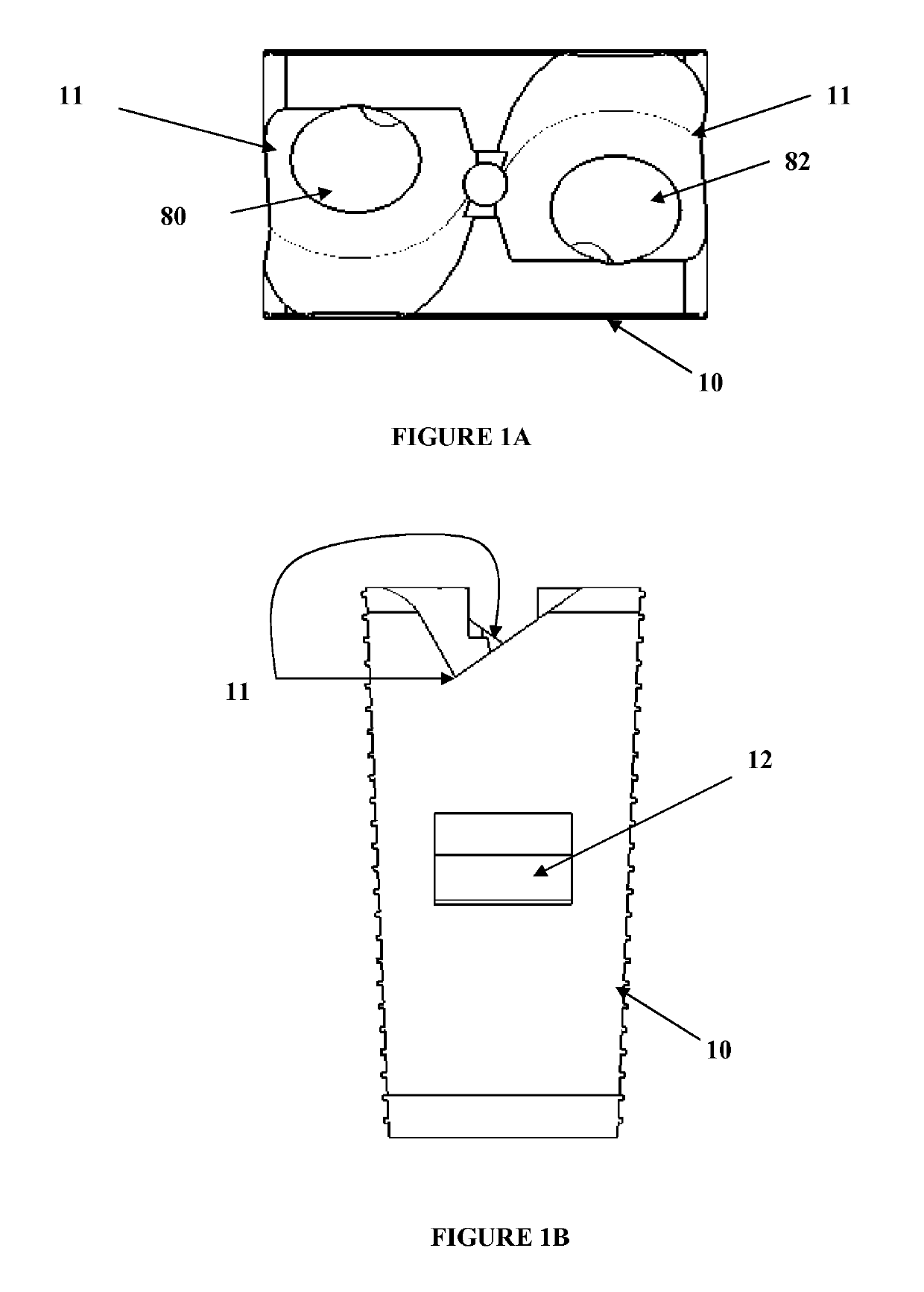
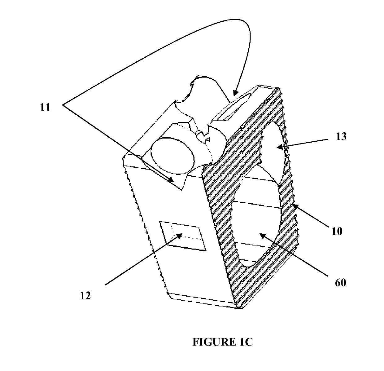
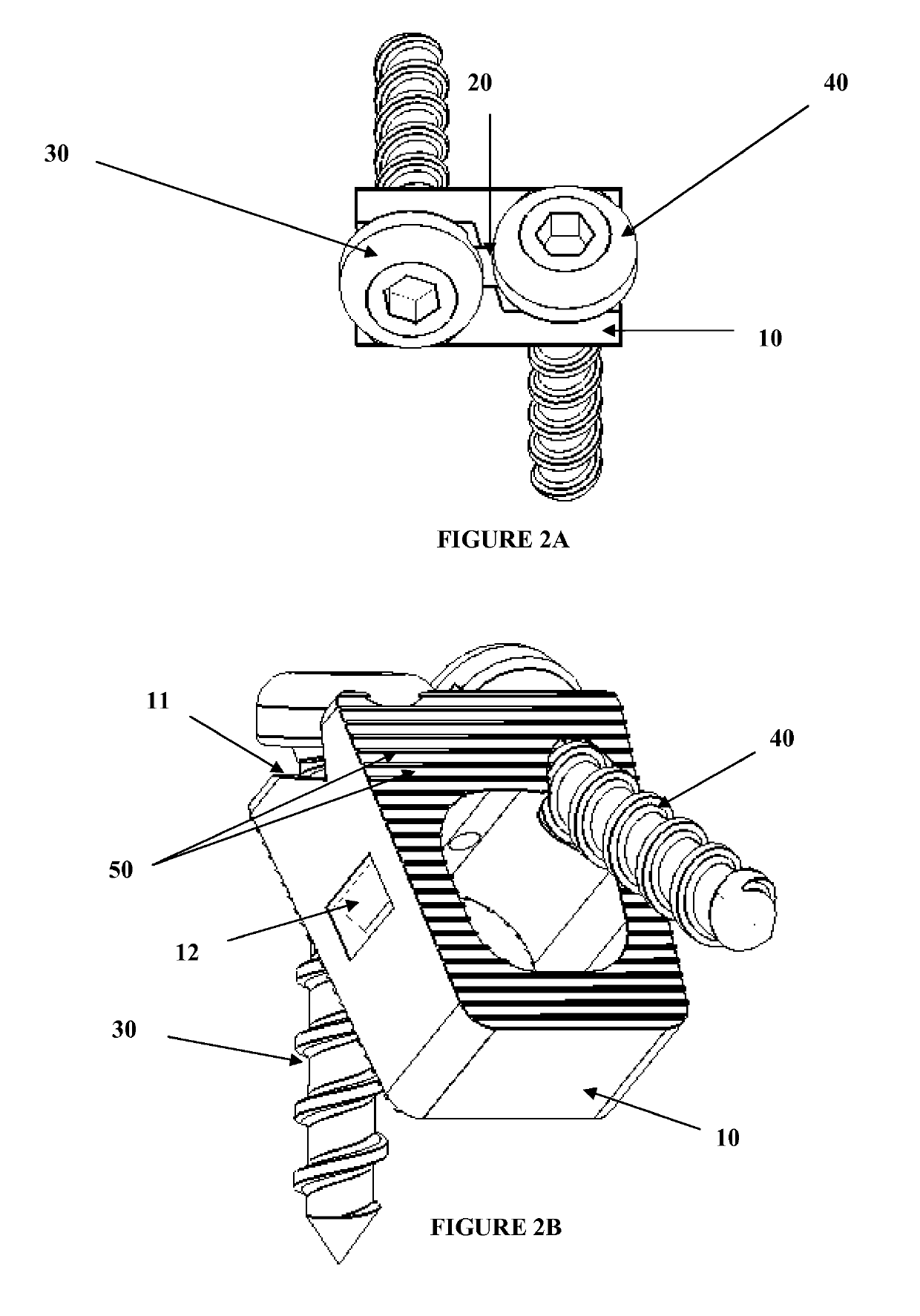
[0060]With reference to FIGS. 1A-7E, exemplary embodiments of the invention will now be described.

[0061]1. Exemplary Medical Device

[0062]Referring to FIGS, 1A-7E, the above described problems of the...


PUM


Abstract

A bi-directional fixating transvertebral (BDFT) screw/cage apparatus is provided. The BDFT apparatus includes an intervertebral cage including a plurality of internal angled screw guides, a plurality of screw members, and a cage indentation adjacent to the screw guides that independently or supplemented by other screw locking mechanisms prevents the screw members from pulling out of the internal angled screw guides. The internal angled screw guides orient a first screw member superiorly and a second screw member inferiorly. The intervertebral cage is adapted for posterior lumbar intervertebral placement, anterior lumbar intervertebral placement, anterio-lateral thoracic intervertebral placement, or anterior cervical intervertebral placement.

Description

[0001]This application is a Continuation-In-Part Application, for which priority is claimed under 35 U.S.C. § 120, of copending U.S. patent application Ser. No. 13 / 103,994, filed on May 9, 2011 (Attorney Docket No. 3003 / 0107PUS8), which is a Divisional of U.S. patent application Ser. No. 12 / 054,335, filed on Mar. 24, 2008 (now U.S. Pat. No. 7,972,363 B2, issued on Jul. 5, 2011) (Attorney Docket No. 3003 / 0107PUS1), which is a Continuation-In-Part of copending application Ser. No. 11 / 842,855, filed on Aug. 21, 2007 (now U.S. Pat. No. 7,942,903, issued May 17, 2011)(Attorney Docket No. 3003 / 0105PUS1), which is a Continuation-In-Part of application Ser. No. 11 / 536,815, filed on Sep. 29, 2006 (now U.S. Pat. No. 7,846,188 B2, issued Dec. 7, 2010) (Attorney Docket No. 3003 / 0104PUS2), which is a Continuation-In-Part of application Ser. No. 11 / 208,644, filed on Aug. 23, 2005 (now U.S. Pat. No. 7,704,279 issued on Apr. 27, 2010)(Attorney Docket No. 3003 / 0104PUS1), the entire contents of all o...

Claims


Application Information

Patent Timeline
Patent Type & Authority Applications(United States)
IPC IPC(8): A61F2/44
CPCA61F2220/0025A61B17/86A61F2002/30772A61F2/447A61B2017/922A61B17/8042A61F2002/2835A61F2002/30787A61F2002/30476A61F2002/448A61B17/7064A61B17/8047A61B17/8605A61F2002/30593
Inventor MOSKOWITZ, NATHAN C.MOSKOWITZ, MOSHEH T.MOSKOWITZ, AHMNON D.ALVARADO, PABLO A. VALDIVIA Y.
Owner MOSKOWITZ FAMILY LLC
Why Eureka
Try Eureka