
Clamp-On Type Ultrasonic Flow Sensor

Active Publication Date: 2019-09-19
KEYENCE
View PDF0 Cites 3 Cited by
  • Summary
  • Abstract
  • Description
  • Claims
  • Application Information

AI Technical Summary

Benefits of technology

The patent describes a method to inspect pipes using ultrasonic waves. When the diameter of the pipe is large or the pipe is made of resin, the ultrasonic elements can be easily placed to separate the fluid components from the unnecessary components and receive them. This reduces the interference of the ultrasonic waves with the pipe's peripheral wall, resulting in more accurate inspection.

Problems solved by technology

When the unnecessary component of the ultrasonic wave is large, it is difficult to accurately calculate a flow rate of the fluid.
However, when the diameter of the pipe is small and the pipe is formed of the metal material, it is not easy to dispose the pair of ultrasonic elements such that the component of the ultrasonic wave passing through the fluid is separated from the unnecessary component and received.
Therefore, a flow rate of the fluid flowing in the metal pipe having the small diameter cannot be calculated.

Method used


Image

  • Clamp-On Type Ultrasonic Flow Sensor
  • Clamp-On Type Ultrasonic Flow Sensor
  • Clamp-On Type Ultrasonic Flow Sensor

Examples


Embodiment Construction

(1) Schematic Configuration of a Clamp-on Type Ultrasonic Flow Sensor

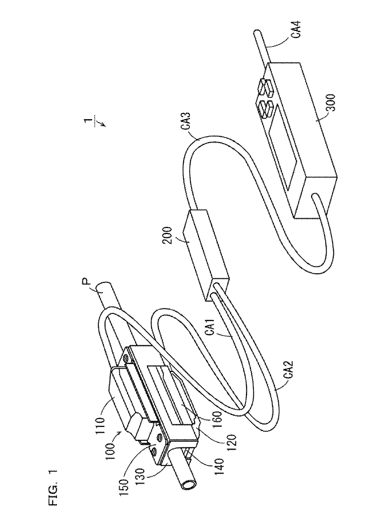
[0042]A clamp-on type ultrasonic flow sensor (hereinafter abbreviated as flow sensor) according to an embodiment of the present invention is explained with reference to the drawings. In the following explanation, a direction along the center axis of a pipe is referred to as axial direction. A direction along a peripheral wall of the pipe is referred to as circumferential direction. A direction inclining with respect to the axial direction by a predetermined angle is referred to as inclining direction. A direction orthogonal to the axial direction and the inclining direction is referred to as width direction. A direction orthogonal to the inclining direction and the width direction is referred to as length direction.

[0043]FIG. 1 is an exterior perspective view of the flow sensor according to the embodiment of the present invention. As shown in FIG. 1, a flow sensor 1 according to this embodiment is configured from a...


PUM


Abstract

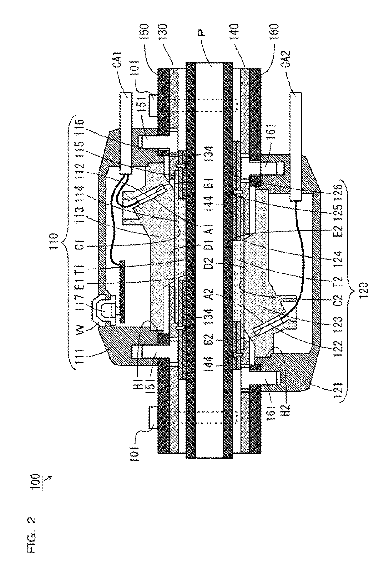
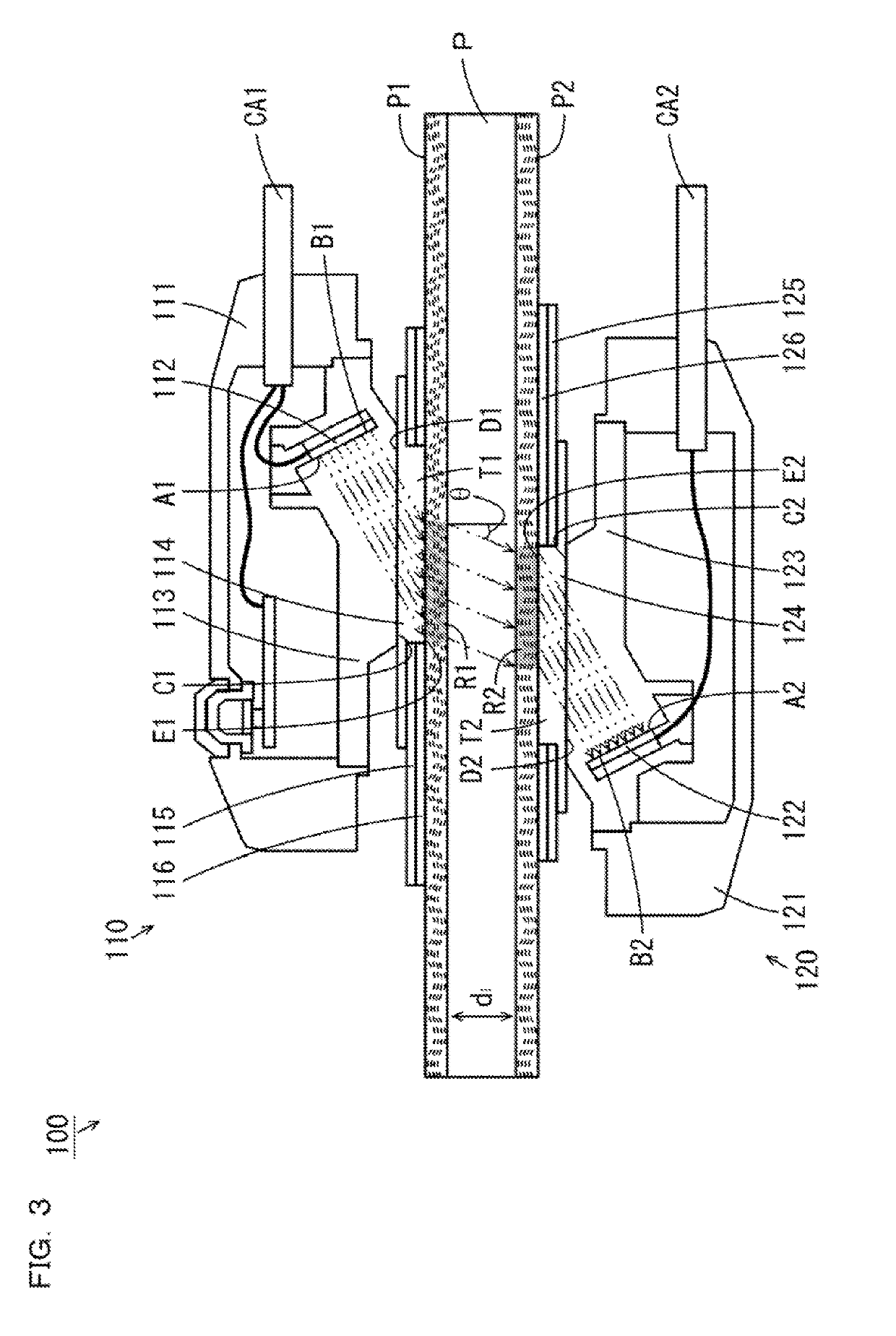
To provide a clamp-on type ultrasonic flow sensor capable of calculating a flow rate of fluid flowing in a pipe. An elastic couplant 114 is supported on a pipe P by a clamp member 130 such that a pipe contact section T1 is in contact with the pipe P. The pipe contact section T1 is surrounded by a damping material 116 between the clamp member 130 and the pipe. An elastic couplant 124 is supported on the pipe by a clamp member 140 such that a pipe contact section T2 is in contact with the pipe. The pipe contact section T2 is surrounded by a damping material 126 between the clamp member 140 and the pipe. The clamp members 130 and 140 are coupled to each other to sandwich the pipe in a state in which the clamp members 130 and 140 respectively press the damping materials 116 and 126.

Description

CROSS-REFERENCE TO RELATED APPLICATIONS[0001]The present application claims foreign priority based on Japanese Patent Application No. 2018-047210, filed Mar. 14, 2018, the contents of which is incorporated herein by reference.BACKGROUND OF THE INVENTION1. Field of the Invention[0002]The present invention relates to a clamp-on type ultrasonic flow sensor that calculates a flow rate of fluid flowing in a pipe.2. Description of Related Art[0003]There is known a clamp-on type ultrasonic flow sensor capable of calculating a flow rate of fluid flowing in a pipe in a state in which the clamp-on type ultrasonic flow sensor is attached to the pipe by a clamp member (see, for example, JP-A-2016-217733 (Patent Literature 1)).[0004]The clamp-on type ultrasonic flow sensor (an ultrasonic flow switch) of Patent Literature 1 includes a pair of ultrasonic elements that performs transmission and reception of an ultrasonic wave. The ultrasonic wave is transmitted to the fluid flowing in the pipe by o...

Claims


Application Information

Patent Timeline
IPC IPC(8): G01F1/66G01F15/18
CPCG01F1/662G01F15/18G01F1/667G01F15/00G01F15/006G01F15/14
Inventor NIIMURA, HIROKAZU
Owner KEYENCE
Learn More