
X-ray utilized compound measuring apparatus

a compound measurement and x-ray technology, applied in the direction of measurement devices, instruments, scientific instruments, etc., can solve the problems of difficult to obtain accurate measurement and difficult to evaluate measurement, and achieve the effect of increasing the accuracy of various measurements and component analysis results

Inactive Publication Date: 2019-09-19
EARTHNIX M INC
View PDF0 Cites 1 Cited by
  • Summary
  • Abstract
  • Description
  • Claims
  • Application Information

AI Technical Summary

Benefits of technology

The present invention aims to improve X-ray utilized compound measuring apparatus by reducing the difficulty of preparing the measurement object and improving accuracy or validity on multiple measurements. The use of a single measuring apparatus enables multiple kinds of measurement under specific conditions, resulting in more accurate and reliable component analysis results.

Problems solved by technology

If such different measurement principles are used, for example, the deviations or errors quantitatively included in the individual measurement values would differ, making it difficult to evaluate the measurement results.
This makes it difficult to obtain an accurate measurement result.

Method used


Image

  • X-ray utilized compound measuring apparatus
  • X-ray utilized compound measuring apparatus
  • X-ray utilized compound measuring apparatus

Examples


first embodiment

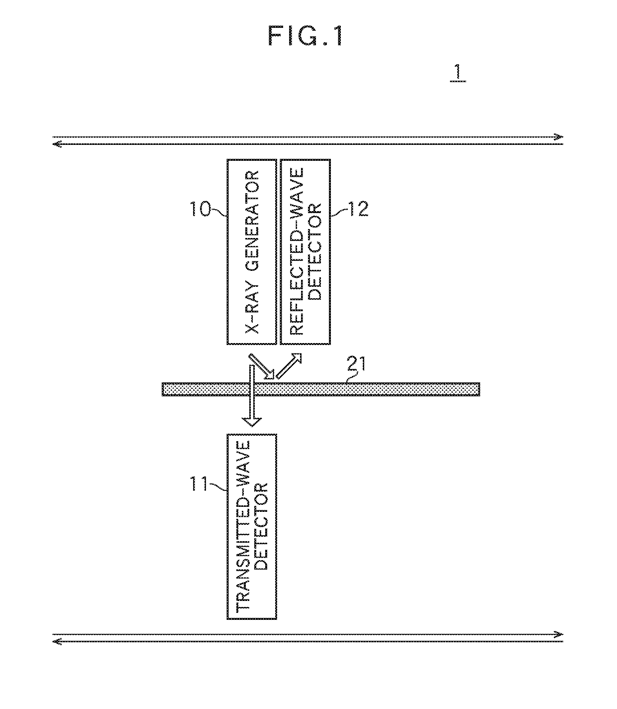
[0020]FIG. 1 is a diagram illustrating, in outline, the configuration of an X-ray utilized compound measuring apparatus 1 according to the first embodiment of the present invention. This diagram illustrates, in outline, the arrangement of an X-ray generator 10, a transmitted-wave detector 11, a reflected-wave detector 12 that constitute the X-ray utilized compound measuring apparatus 1 when performing predetermined measurement by applying X-rays to a measurement object 21, illustrating a state in which the measurement object 21 to be measured using these components.

[0021]The X-ray generator 10 and the reflected-wave detector 12 are disposed so that an X-ray emitting portion of the X-ray generator 10 and an X-ray detecting portion of the reflected-wave detector 12 are positioned side by side.

[0022]The transmitted-wave detector 11 is opposed to the X-ray generator 10, with a certain distance therebetween, so that an X-ray detecting portion of the transmitted-wave detector 11 and the X...

second embodiment

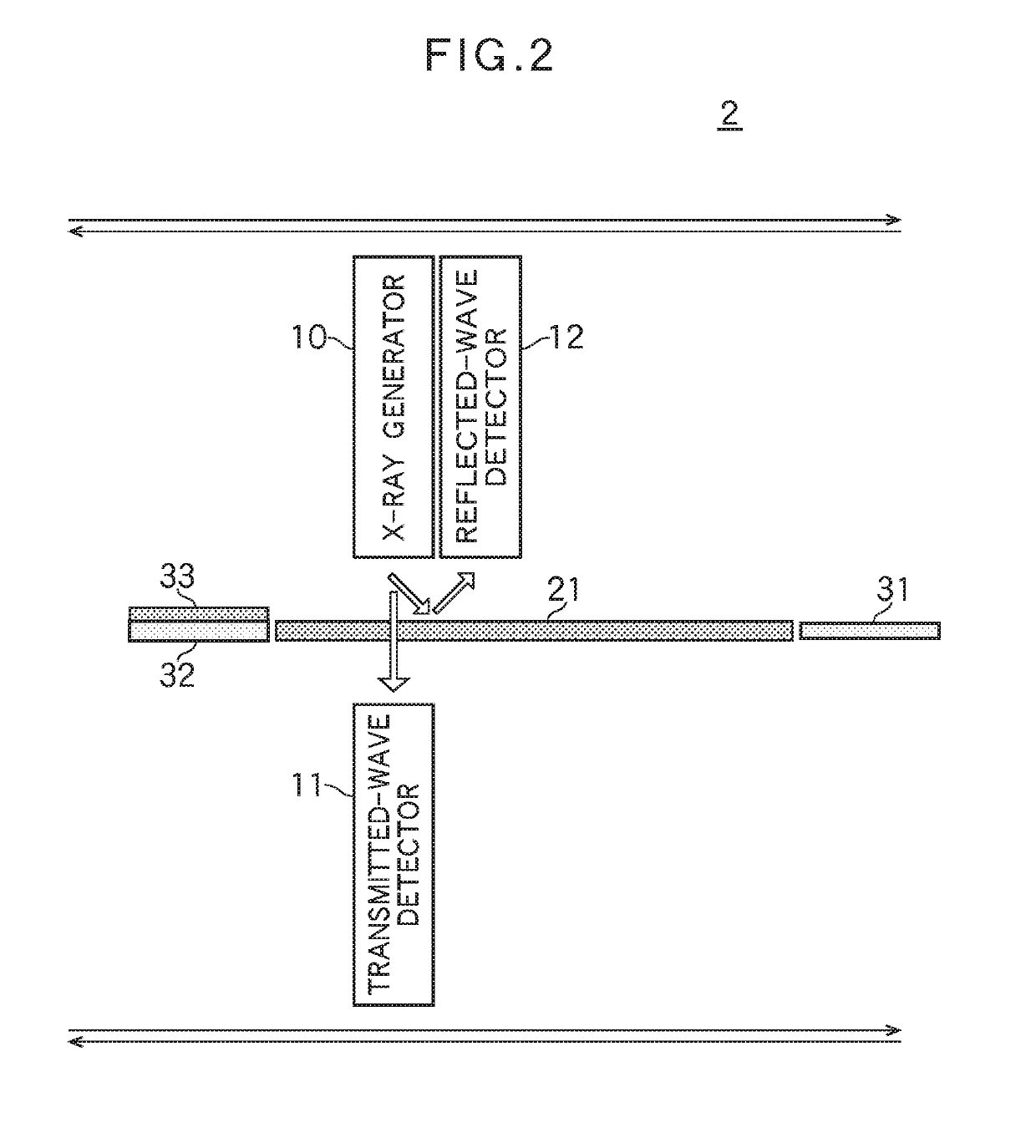
[0045]FIG. 2 is a diagram illustrating, in outline, the configuration of an X-ray utilized compound measuring apparatus 2 according to the second embodiment of the present invention.

[0046]This diagram illustrates, in outline, the configuration of an X-ray generator 10, a transmitted-wave detector 11, a reflected-wave detector 12, the first calibration board 31, and the second calibration board 32 that constitute the X-ray utilized compound measuring apparatus 2 in performing predetermined measurement by applying X-rays to the measurement object 21, illustrating a state in which the measurement object 21 to be measured using these components.

[0047]The X-ray utilized compound measuring apparatus 2 in FIG. 2 is provided with the X-ray generator 10, the transmitted-wave detector 11, the reflected-wave detector 12, and a moving mechanism (not illustrated) for moving the above components, like the apparatus illustrated in FIG. 1. The above components are configured so as to be equivalent ...

third embodiment

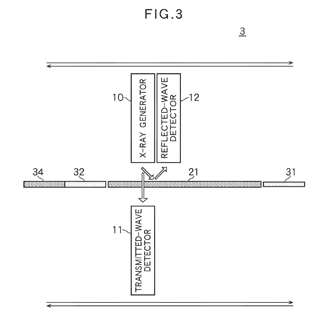
[0069]FIG. 3 is a diagram illustrating, in outline, the configuration of an X-ray utilized compound measuring apparatus 3 according to the third embodiment of the present invention.

[0070]This diagram illustrates, in outline, the arrangement of an X-ray generator 10, a transmitted-wave detector 11, a reflected-wave detector 12, the first calibration board 31, the second calibration board 32, and a calibration board 34 for component analysis that constitute the X-ray utilized compound measuring apparatus 3 in performing predetermined measurement by applying X-rays to the measurement object 21, illustrating a state in which the measurement object 21 to be measured using these components.

[0071]The X-ray utilized compound measuring apparatus 3 in FIG. 3 comprises the X-ray generator 10, the transmitted-wave detector 11, the reflected-wave detector 12, and a moving mechanism (not illustrated) for moving the above components, like the apparatus illustrated in FIG. 1. The above components a...


PUM


Abstract

There is provided an X-ray utilized compound measuring apparatus in which troublesome tasks required to dispose a measurement object are reduced and the accuracy or the validity of measurements on multiple kinds of measurement can be improved. The X-ray utilized compound measuring apparatus comprises an X-ray generator 10 that outputs X-rays, a reflected-wave detector 12 that detects a reflected wave of the X-rays emitted from the X-ray generator 10 and reflected by a measurement object 21, a transmitted-wave detector 11 that detects a transmitted wave of the X-rays emitted from the X-ray generator 10 and passing through the measurement object 21, and a control unit that controls the X-ray generator 10 to output X-rays and performs computational processing for obtaining measurement values of a plurality of items on the measurement object 21 using a reflected-wave detection signal output from the reflected-wave detector 12 and representing the reflected wave and a transmitted-wave detection signal output from the transmitted-wave detector 11 and representing the transmitted wave and also performs computational processing for component analysis.

Description

1. FILED OF THE INVENTION[0001]The present invention relates to X-ray utilized compound measuring apparatus that apply X-rays to an object to be measured to measure the thickness of the measurement object and / or analyze the component of the measurement object.[0002]To measure the thickness of a sheet-like member, such as a film of resin or the like, a paper material, a pulp, or a board, measuring apparatuses that passes X-rays, β rays, or γ rays therethrough are used.[0003]This through-beam type measuring apparatus is configured to emit X-rays or the like from an X-ray emitting unit or the like to an object to be measure (a sample) and detect the X-rays or the like that have passed through the measurement object with a detecting unit to enable, for example, acquisition of a transmission image or observation of cell activity (for example, see Patent Literature 1).[PTL][Patent Literature 1] Japanese Unexamined Patent Application Publication No. 2015-90311SUMMARY OF THE INVENTION[0004]...

Claims


Application Information

Patent Timeline
IPC IPC(8): G01N23/223G01N23/04G01B11/06
CPCG01N23/223G01B11/06G01N23/04G01N23/20083G01N2223/045G01N2223/1016G01N2223/303G01N2223/3303G01N2223/61G01N2223/613G01N2223/622
Inventor UCHIDA, HIROSHIEMURA, TAKASHIOGAWA, JUNICHINAKANISHI, RYUSUKE
Owner EARTHNIX M INC
Learn More