Breaker device for connection to an electrical circuit

a technology of breaker device and electrical circuit, which is applied in the direction of electrical equipment, conductor severing switch, basic electric elements, etc., can solve the problems of inability to fully break, inability to accept damage to the electrical system, and may take a relatively long time for fuses to break

Active Publication Date: 2019-09-19
ARIANEGRP SAS
View PDF0 Cites 5 Cited by
  • Summary
  • Abstract
  • Description
  • Claims
  • Application Information

AI Technical Summary

Benefits of technology

[0012]Advantageously, at least one resistor or diode may be connected in series in the line connecting the device for igniting the initiator to one of the terminals of the fusible element.
[0013]Such an embodiment serves advantageously to avoid any risk of the igniter device being degraded by the current flowing therethrough.
[0014]In an embodiment, the fusible element may be a separate component connected to the conductive portion. Under such circumstances, the fusible element constitutes an element that is distinct from the conductive portion and that is connected in series therewith, e.g. by soldering.
[0015]In a variant, the fusible element may be constituted by a narrow zone of the conductive portion. Under such circumstances, the conductive portion and the fusible element are constituted by the same material.
[0016]In an embodiment, the pressurizing chamber constitutes a first break...

Problems solved by technology

Nevertheless, for currents that are only a little greater than the nominal currents, such fuses may take a relatively long time to break and may possibly break incompletely.
A bre...

Method used


Image

  • Breaker device for connection to an electrical circuit
  • Breaker device for connection to an electrical circuit
  • Breaker device for connection to an electrical circuit

Examples


Embodiment Construction

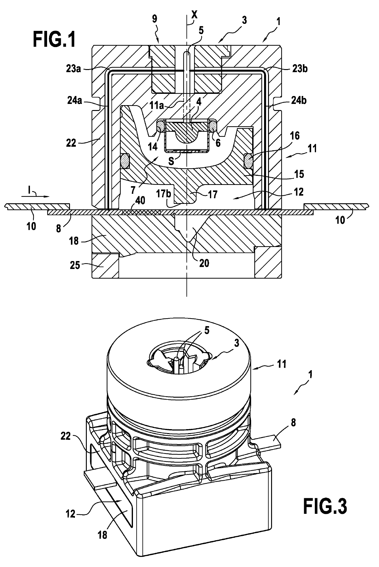
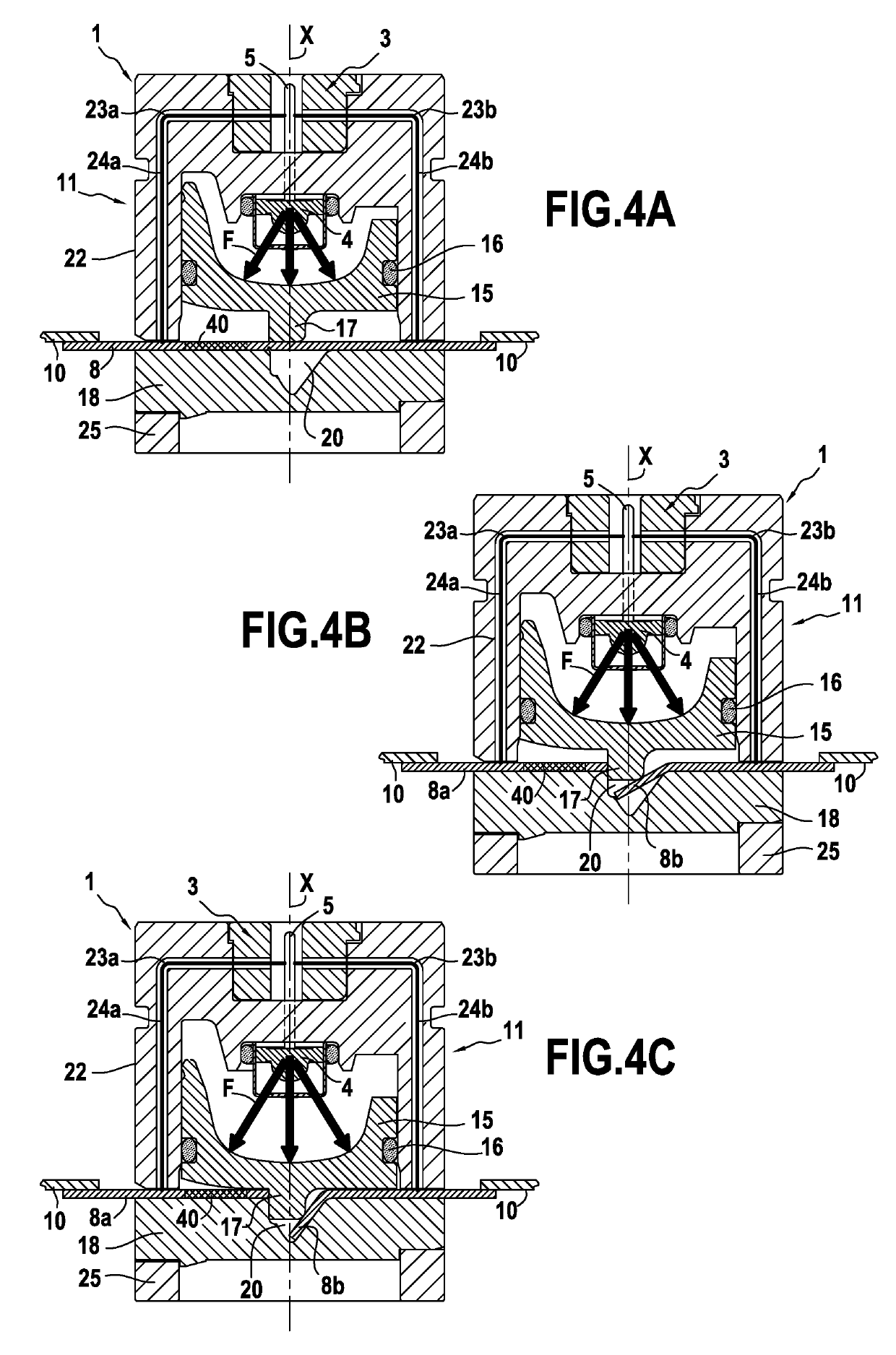
[0047]FIG. 1 is a section view of an example breaker device 1 of the invention. As described in detail below, in the example breaker device 1 shown in FIG. 1, the conductive portion breaks when the device 1 goes from the first configuration to the second configuration. Other arrangements are possible in the context of the present invention, as described below.

[0048]In FIG. 1, the device 1 is in the first configuration, i.e. a configuration in which electric current (arrow I) can flow in the phase 10 of the power supply circuit and in the conductive portion 8. In the example shown, the power supply circuit has a single phase and the breaker device 1 has a single conductive portion 8. Nevertheless, it would not go beyond the ambit of the invention for the circuit to have a plurality of phases and the breaker device to have a plurality of conductive portions, and one such embodiment is mentioned below.

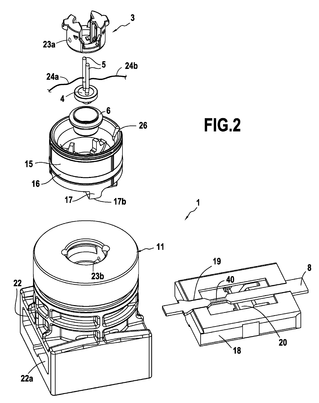
[0049]The breaker device 1 comprises a pyrotechnic initiator 3 having an igniter devi...


PUM


Abstract

A breaker device for connecting in an electrical circuit, the device includes a pyrotechnic initiator and a body having present therein: a pressurizing chamber in communication with an outlet from the pyrotechnic initiator; at least one electrically conductive portion for connection to the electrical circuit; at least one fusible element connected in series with the conductive portion, the initiator being connected to the terminals of the fusible element and the fusible element being configured to trip when the current passing through it exceeds a predetermined value, thereby actuating the initiator; and a movable breaker element; the pyrotechnic initiator being configured to cause the breaker device to pass from a current-passing first configuration to a circuit-breaking second configuration, the movable breaker element being moved on passing from the first configuration to the second in order to disconnect the conductive portion.

Description

BACKGROUND OF THE INVENTION[0001]The invention relates to a breaker device for interrupting electric current flowing in an electrical circuit, and also to a secure electrical system including such a breaker device.[0002]Electrical circuits may be protected at present by placing fuses in each of the phases. Such fuses serve to interrupt the electric current in the event of a high current appearing for a specific duration, and they are reliable in use in the case of faults with high fault currents. Nevertheless, for currents that are only a little greater than the nominal currents, such fuses may take a relatively long time to break and may possibly break incompletely. A break that is incomplete or that takes place too late can lead to unacceptable damage to the electrical system, and in particular to an electrical device powered by the electrical circuit. It is therefore desirable to improve the quality of the circuit breaking performed in the event of a malfunction occurring so as t...

Claims


Application Information

Patent Timeline
IPC IPC(8): H01H85/10H01H85/02
CPCH01H85/10H01H85/0241H01H2085/0555H01H39/006H01H85/0039
Inventor GONTHIER, GILLESMARLIN, FRÉDÉRICDE PALMA, JEAN-FRANÇOISOUAIDA, RÉMY
Owner ARIANEGRP SAS
Why Eureka
Try Eureka