
Femoral hip joint spacer with irrigation device

a technology irrigation device, which is applied in the field of femoral hip joint spacer, can solve the problems of inability to adjust the concentration of antimicrobially active ingredients in the bodily fluid surrounding the spacer, inability to change the type and number of antibiotics used, and inability to prolong the service life of the spacer, so as to prevent the shortening of the tendons and muscles, and reduce the rehabilitation time.

Active Publication Date: 2019-09-26
HERAEUS MEDICAL
View PDF2 Cites 33 Cited by
  • Summary
  • Abstract
  • Description
  • Claims
  • Application Information

AI Technical Summary

Benefits of technology

The present invention relates to a hip joint spacer that can be used in orthopedic surgery. The invention provides a solution to prevent infections and promote faster recovery after surgery by using an antimicrobial active ingredient solution. Additionally, the invention allows for the adjustment of the active ingredient concentration and the variation of the type and number of microbial active ingredients even after implantation of the hip joint spacer. The invention also allows for movement of the hip joint to prevent tendons and muscles from shortening and degeneration, which helps in reducing rehabilitation time.

Problems solved by technology

Unfortunately, in a small percentage of cases, hip joint endoprostheses are colonized by microbial microorganisms, particularly Gram-positive bacteria and also Gram-negative bacteria, and to a very small extent by yeasts and fungi.
Where hip joint endoprostheses are colonized by microbial microorganisms, the surrounding bone and soft tissue also become infected and damaged by the microbial microorganisms.
In the case of spacers hitherto manufactured from bone cement, a subsequent change in the type and number of antibiotics used is not possible after spacer production or after implantation.
It is moreover likewise impossible to adjust a defined concentration of antimicrobially active ingredients in the wound secretions or the bodily fluid surrounding the spacer.
This means that a proportion of the antimicrobial active ingredients for protecting the spacer surface from microbial colonization are lost.

Method used


Image

  • Femoral hip joint spacer with irrigation device
  • Femoral hip joint spacer with irrigation device
  • Femoral hip joint spacer with irrigation device

Examples


Embodiment Construction

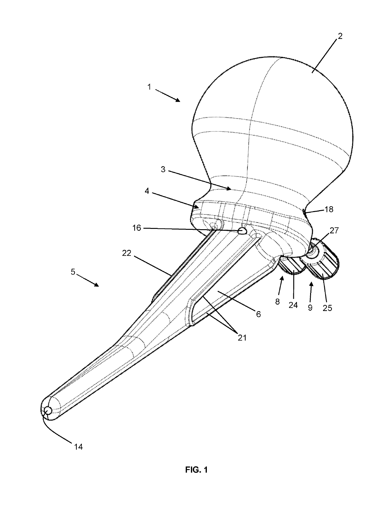
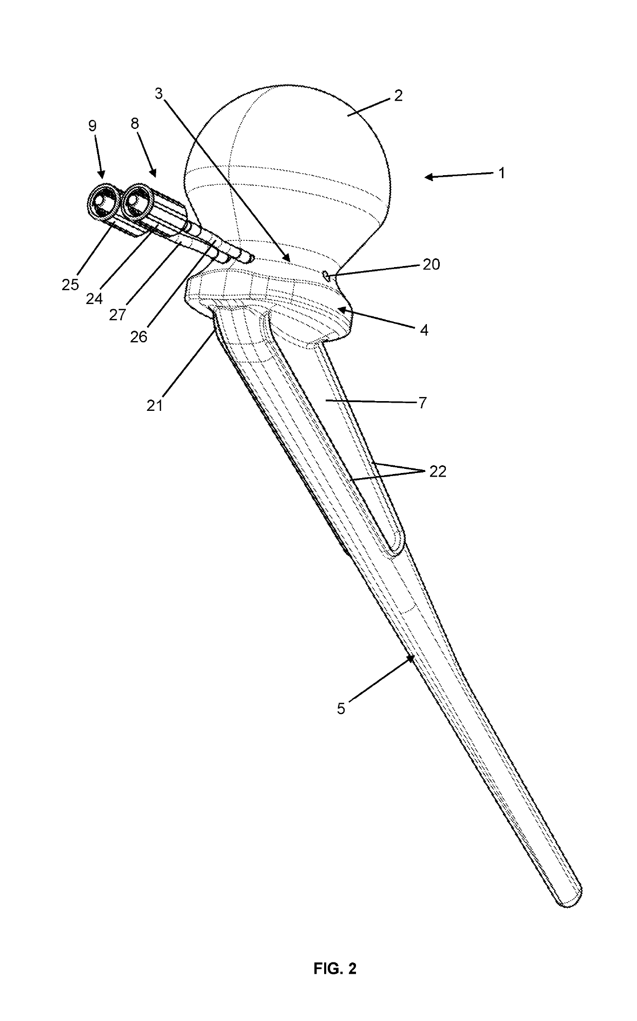
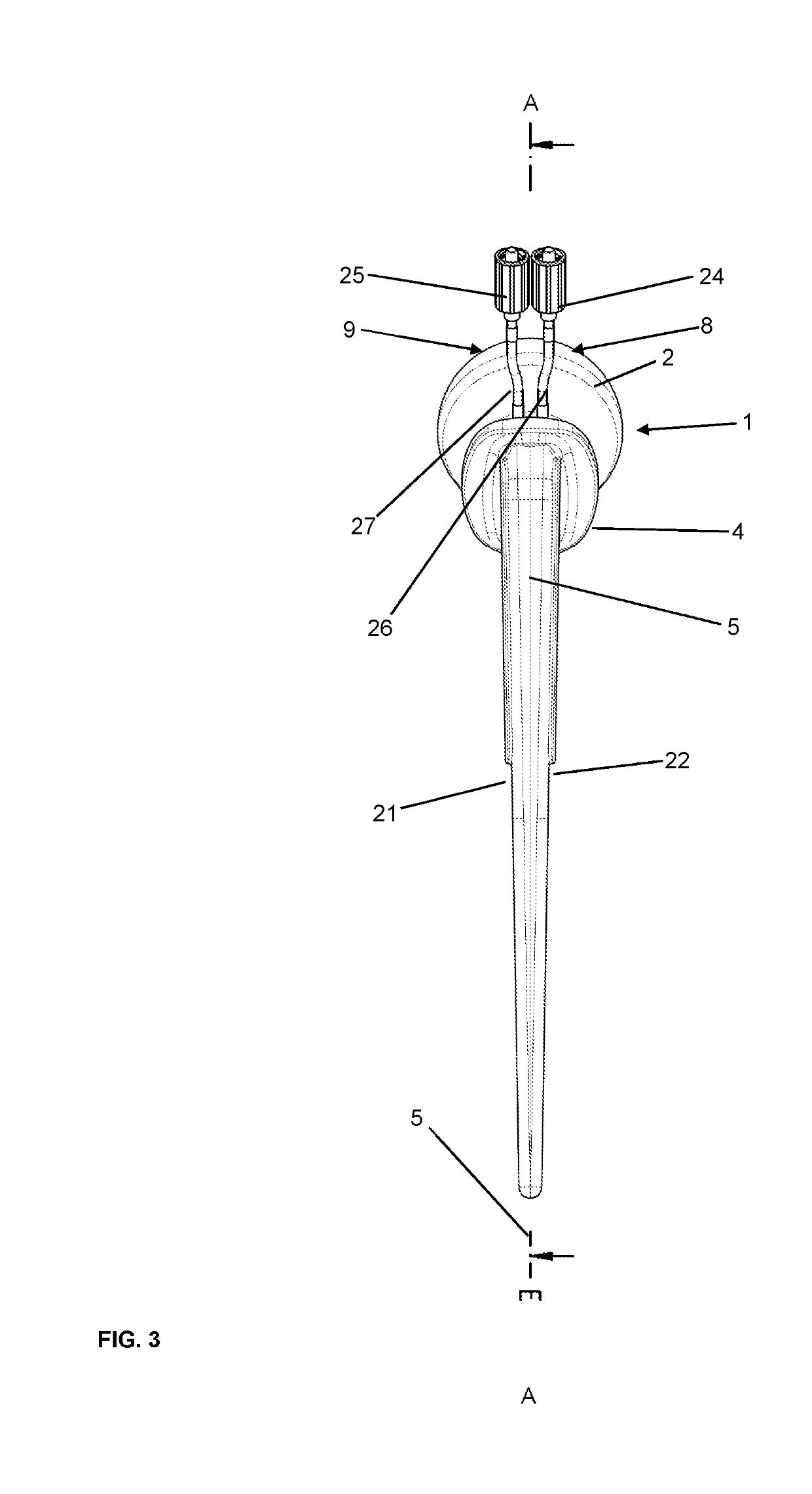
[0118]FIGS. 1 to 7 show depictions of a first exemplary embodiment of a hip joint spacer according to the invention with an irrigation device. The femoral hip joint spacer (i.e., the hip joint spacer replicating the joint head of the femur and intended to be fastened to the femur) has a ball head 1 with a sliding surface 2 on the proximal side. The sliding surface 2 lies when inserted (i.e., when inserted into the patient) against the hip joint socket and so forms part of the hip joint. On the distal side opposite the sliding surface 2, the ball head 1 is connected to a collar 4 via a neck 3. The neck 3 is thinner than the ball head 1 and the collar 4. On the distal side of the collar 4 a stem 5 is attached, which extends in the distal direction and serves in fastening the hip joint spacer in the femur. To this end, the hip joint spacer has fastening areas 6, 7 on two opposing sides of the stem 5, these being provided to connect the hip joint spacer to the femur with the aid of bone...


PUM


Abstract

A femoral hip joint spacer including a prosthesis body having a ball head with a sliding surface, a neck, a collar and a stem. A fastening area is arranged on the stem. The femoral hip joint spacer further has a first connector for feeding a medical irrigation liquid into the body, a second connector for draining the irrigation liquid from the body, and an irrigation liquid inlet opening. The first connector is connected in a liquid-conveying manner to the irrigation liquid inlet opening and an irrigation liquid outlet opening. The second connector is connected in a liquid-conveying manner to the irrigation liquid outlet opening, an irrigation liquid discharge opening and an irrigation liquid intake opening. The irrigation liquid discharge opening is connected inside the body to the irrigation liquid inlet opening and the irrigation liquid intake opening is connected inside the body to the irrigation liquid outlet opening.

Description

RELATED APPLICATION[0001]This application claims the benefit of priority to German Patent Application Number DE 10 2018 106 705.4, filed on Mar. 21, 2018, the contents of which are incorporated in this application by reference.TECHNICAL FIELD[0002]The invention relates to a femoral hip joint spacer for temporary replacement of at least one part of a hip joint, which is intended for the interim phase of two-stage septic revisions of hip joint endoprostheses. The hip joint spacer may be used in particular in two-stage septic revisions in which two or more microbial microorganisms are the cause of an infection in the hip joint endoprosthesis and the surrounding tissue.BACKGROUND OF THE DISCLOSURE[0003]Hip joint endoprostheses are implanted in large numbers worldwide. Unfortunately, in a small percentage of cases, hip joint endoprostheses are colonized by microbial microorganisms, particularly Gram-positive bacteria and also Gram-negative bacteria, and to a very small extent by yeasts a...

Claims


Application Information

Patent Timeline
IPC IPC(8): A61M3/02A61F2/46A61M39/24A61M39/10
CPCA61F2002/4615A61F2002/30649A61M39/24A61F2/4607A61M39/10A61M2205/04A61F2/4684A61F2002/3613A61M3/0283A61F2/32A61F2002/30677A61F2250/0067A61F2/36A61F2002/30672A61F2002/3627A61F2002/30805A61F2002/4631A61F2/4675A61F2002/30405
Inventor VOGT, SEBASTIANKLUGE, THOMAS
Owner HERAEUS MEDICAL
Learn More