Drawing-out tool for sheet metal

Active Publication Date: 2019-10-10
STAR
View PDF0 Cites 2 Cited by
  • Summary
  • Abstract
  • Description
  • Claims
  • Application Information

AI Technical Summary

Benefits of technology

[0012]According to the present invention, the following advantages may be obtained.
[0013](1) By forming a space (first space) and a power source accommodating space (second space) partitioned by the space and division walls in a housing, and by accommodating, in the first space, an energization part body of an energization mechanism, on the other hand, by accommodating a power source for light source in the second space, and by shielding the dust, metal dust, and soil dust from mingling in and attaching to the electric system to evade the generation of the trouble to the electric system, a drawing-out tool for sheet metal that is less in the failure and excellent in the durability, and has excellent handling property may be obtained.
[0014](2) A drawing-out tool for sheet metal which may secure sufficient brightness during the sheet metal process, may clearly grasp the relief on the sheet metal surface in the neighborhood of a bit nece

Problems solved by technology

Furthermore, the working field of the sheet metal process is generally not guaranteed with sufficient lighting, therefore, in order to make it possible to perform the sheet metal process efficiently in a short time even in a dark working field, at least, (1) sufficient lighting is secured during the sheet metal process, and (2) an operator can visually clearly observe unevenness of a sheet metal surface are desired from the viewpoint of an operation environment are desired.
In this point, a drawing-out tool for sheet metal shown in JP 5716889 B1 is not necessarily sufficient in protection of an electric system of an energization mechanism for supplying electric current to a bit, furthermore, the drawing-out tool for sheet metal itself is not provided with a means for illuminating a sheet metal surface.
Therefore, there are risks such that (1) a trouble is generated when dust, metal dust, and soil dust mingle in or attach to an electric system of an energization mechanism for supplying electric current to the bit (for example, a contact failure that is generated when dust, metal dust, and

Method used


Image

  • Drawing-out tool for sheet metal
  • Drawing-out tool for sheet metal
  • Drawing-out tool for sheet metal

Examples


Example

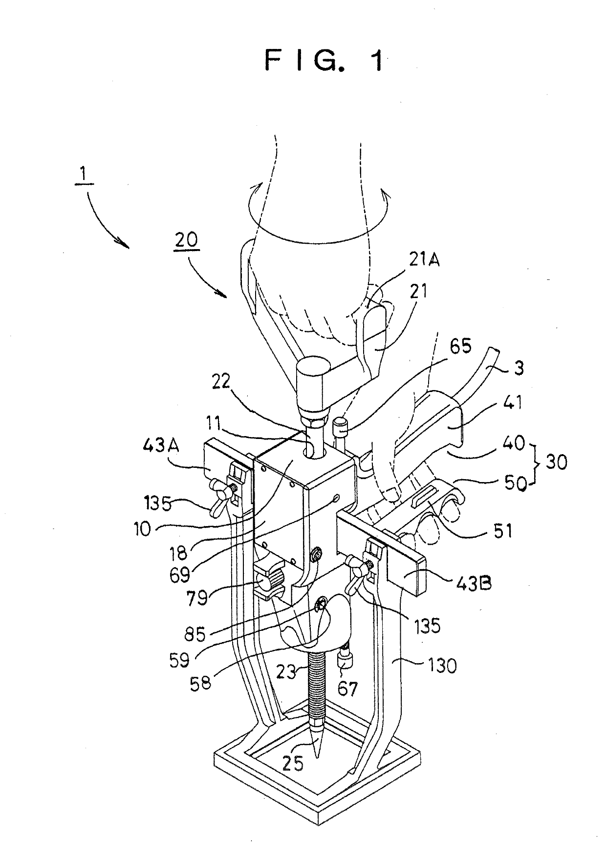
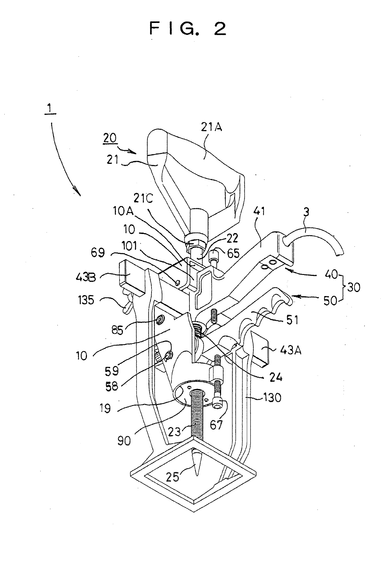
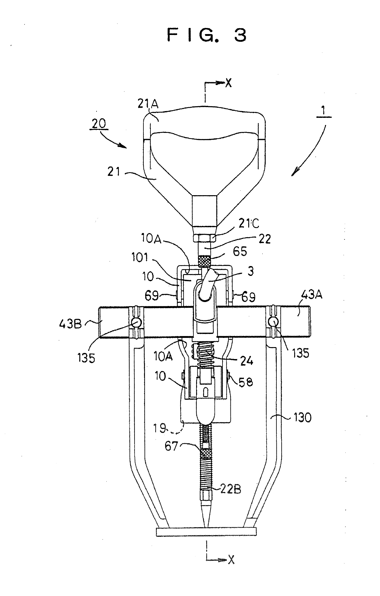
[0042]A drawing-out tool for sheet metal according to the present invention includes: a center shaft; a first operation means provided with a bit arranged to an apex part of the center shaft and weldable to a sheet metal surface; a second operation means for pulling-up the first operation means; an energization mechanism for supplying electric current to the bit; and a leg body for supporting the second operation means, wherein a housing for accommodating an illumination unit and the illumination unit for illuminating the sheet metal surface accommodated in the housing are provided.

[0043]The housing preferably includes: a space for accommodating the energization mechanism; and a power source accommodating part for accommodating a power source for a light source constituting the illumination unit.

[0044]The illumination unit preferably includes: a light source incorporated in the housing; a power source for the light source for supplying electric power to the light source; and a light...


PUM

PropertyMeasurementUnit
Volumeaaaaaaaaaa
Areaaaaaaaaaaa
Durabilityaaaaaaaaaa

Abstract

To provide a drawing-out tool for sheet metal which is less in failure and excellent in the durability and has excellent handling property by evading generation of trouble in an electric system by shielding dust, metal dust, soil dust or the like from mingling in or attaching to the electric system. The drawing-out tool for sheet metal comprises a center shaft (22); a first operation means (20) provided with a bit (25) arranged to an apex part of the center shaft; a second operation means (30) for pulling-up the first operation means; and an energization mechanism (100) for supplying electric current to the bit are provided. The housing (10) for accommodating the illumination unit (70) and the illumination unit for illuminating a sheet metal surface accommodated in the housing are included.

Description

CROSS REFERENCE TO THE RELATED APPLICATIONS[0001]This application is based on and claims priority to Japanese patent application No. 2018-84530, filed Apr. 8, 2018, the entire disclosure of which is herein incorporated by reference as a part of this application and to Japanese patent application No. 2018-145443, filed Jul. 13, 2018, the entire disclosure of which is herein incorporated by reference as a part of this application.BACKGROUND OF THE INVENTION[0002]The present invention relates to a drawing-out tool for sheet metal for drawing-out a recess part on a sheet metal surface during sheet metal process.[0003]So far, as a drawing-out tool for sheet metal for drawing-out a recess part on a sheet metal surface during sheet metal process, a drawing-out tool for sheet metal for drawing-out while applying a fine force to an apex of a bit for welding on the sheet metal surface has been proposed by the present inventors (JP 5716889 B1).[0004]A drawing-out tool for sheet metal shown in ...

Claims


Application Information

Patent Timeline
IPC IPC(8): B21D31/00B21D22/20B21D35/00B21D11/20B21D11/22B21D53/36
CPCB21D11/20B21D31/005B21D22/20B21D35/002B21D53/36B21D11/22B21D1/06B21D1/12B21D1/08
Inventor ISHIHARA, KOSEI
Owner STAR
Why Eureka
Try Eureka