Caster with braking device

a braking device and caster technology, applied in the field of casters, can solve the problems of relatively low mechanical load capacity, high cost, complicated mechanical structure, etc., and achieve the effect of greater braking torqu

Active Publication Date: 2019-10-10
GROSS FROELICH
View PDF14 Cites 1 Cited by
  • Summary
  • Abstract
  • Description
  • Claims
  • Application Information

AI Technical Summary

Benefits of technology

[0008]According to a first variant of the present disclosure, the braking device further comprises at least one spring element which cooperates with the at least one resilient housing portion, enhancing the braking force effect and / or increasing the mechanical load capacity of the at least one resilient housing portion. The housing, or at least the resilient housing portion, is preferably made of a plastic, for example polypropylene or polyamide. Suitably, the at least one spring element is made of metal, of a fiber-reinforced plastic, or of another material with a higher mechanical load capacity than the at least one resilient housing portion.
[0009]The at least one spring element can be designed, according to a first exemplary embodiment, as a leaf spring which is embedded in the material of the at least one resilient housing portion. This is expediently achieved by arranging the spring element as an insert part in an injection mold for the caster housing, and then molding the insert. The advantage of this is that the spring element has no direct contact with the axle pin, and accordingly does not generate any noise or cause any wear. However, the at least one spring element can also project beyond the at least one resilient housing portion in the direction of the at least one wheel, and the end regions of the spring element can then be coated or otherwise configured to prevent noise and wear.
[0014]According to a further variant of the present disclosure, there is a resilient housing portion which does not act on the axle pin—but rather receives it. That is, the housing opening oriented substantially horizontally is formed in a housing portion which is elastically vertically displaceable relative to the rest of the housing. The housing opening which receives the axle pin is not formed in this case as an elongated hole, since the axle pin need not be displaced inside it. This is advantageous for the wear behavior of the opening, and thus the caster housing. In order to achieve the resilient displaceability of the housing portion, the housing portion can preferably be integrally connected via spring webs to the rest of the housing. The possible vertical displacement path of the housing portion is advantageously defined by a gap provided above the housing portion. An elastically compressible molded part or a leaf spring can be arranged in the gap as a way of influencing the force required to displace the housing portion. Different materials or material quantities or geometries enable an adjustment of the desired result. Since the caster housing can be designed in the relevant area to be comparatively narrow or thin-walled, a lateral housing surface can have at least one laterally-protruding projection which serves as a stop for the housing portion, and / or enlarges the stop surface for the housing portion.
[0016]The braking device of the two latter embodiment variants expediently has at least one projection which protrudes laterally beyond a lateral housing surface and acts as a brake shoe, arranged radially inward relative to a wheel jacket of the at least one wheel, in such a manner that a braking surface of the projection works together with a force fit or a positive fit with the radially-inner region of the wheel jacket in the first load state. Because of the greater distance of this braking surface from the wheel center, compared to that of the embodiments mentioned first, it is possible to generate greater braking torque.

Problems solved by technology

However, some of these are very mechanically complicated, and thus costly.
This simple solution is very inexpensive, but has the disadvantage of relatively low mechanical load capacity, especially in the tests performed by manufacturers in which an impact is directed on the axle and thus the spring.

Method used


Image

  • Caster with braking device
  • Caster with braking device
  • Caster with braking device

Examples


Embodiment Construction

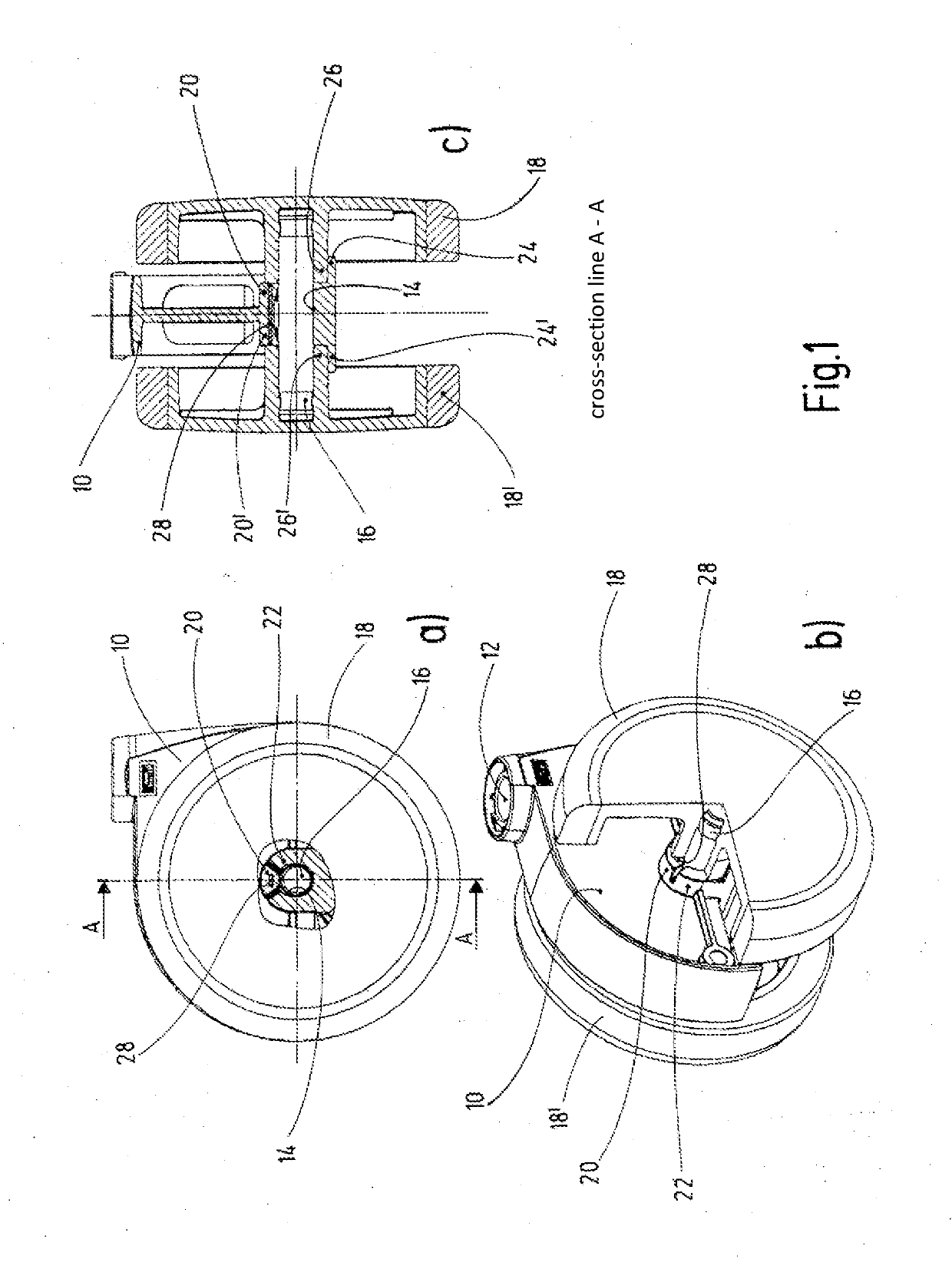
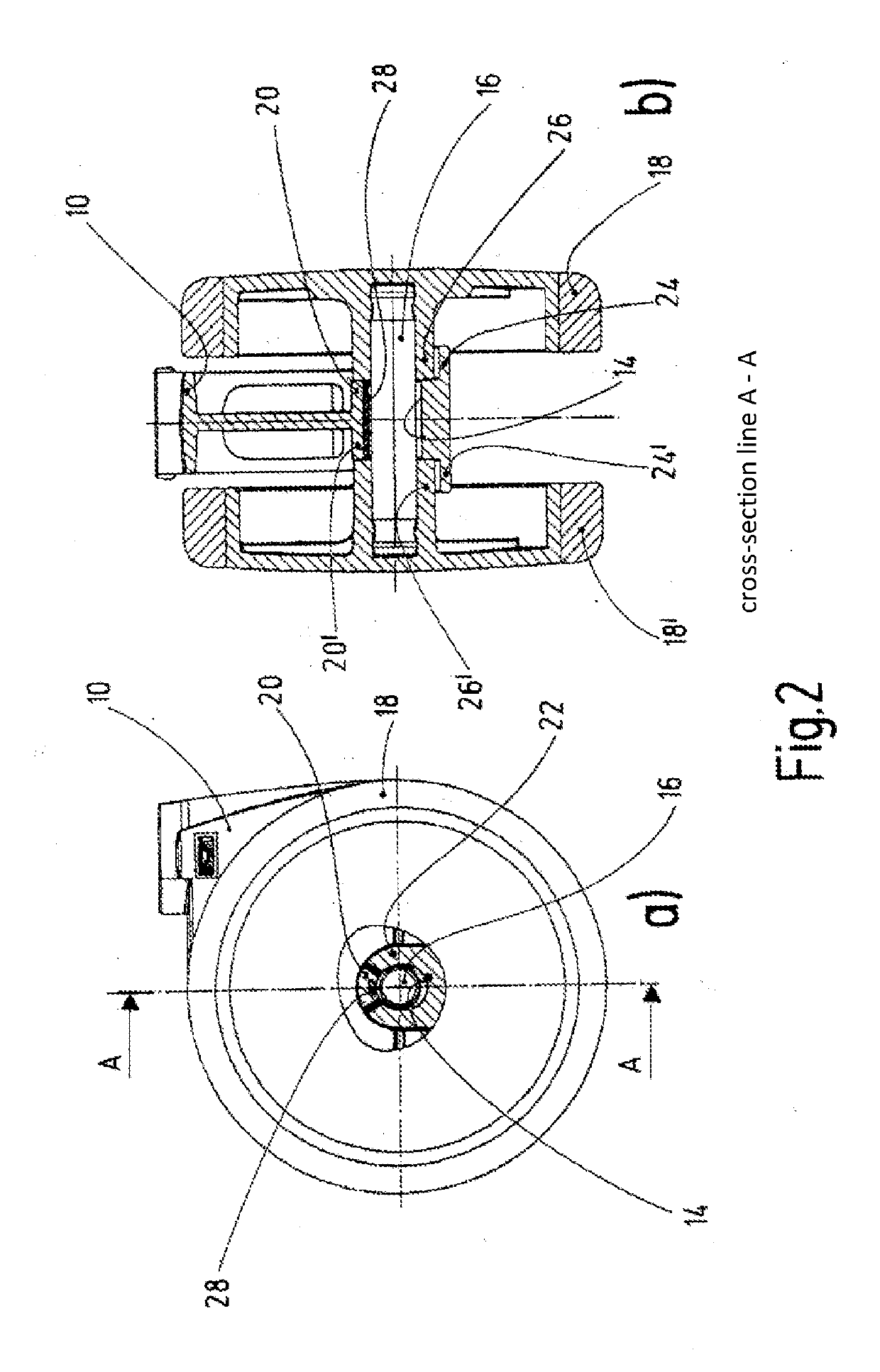
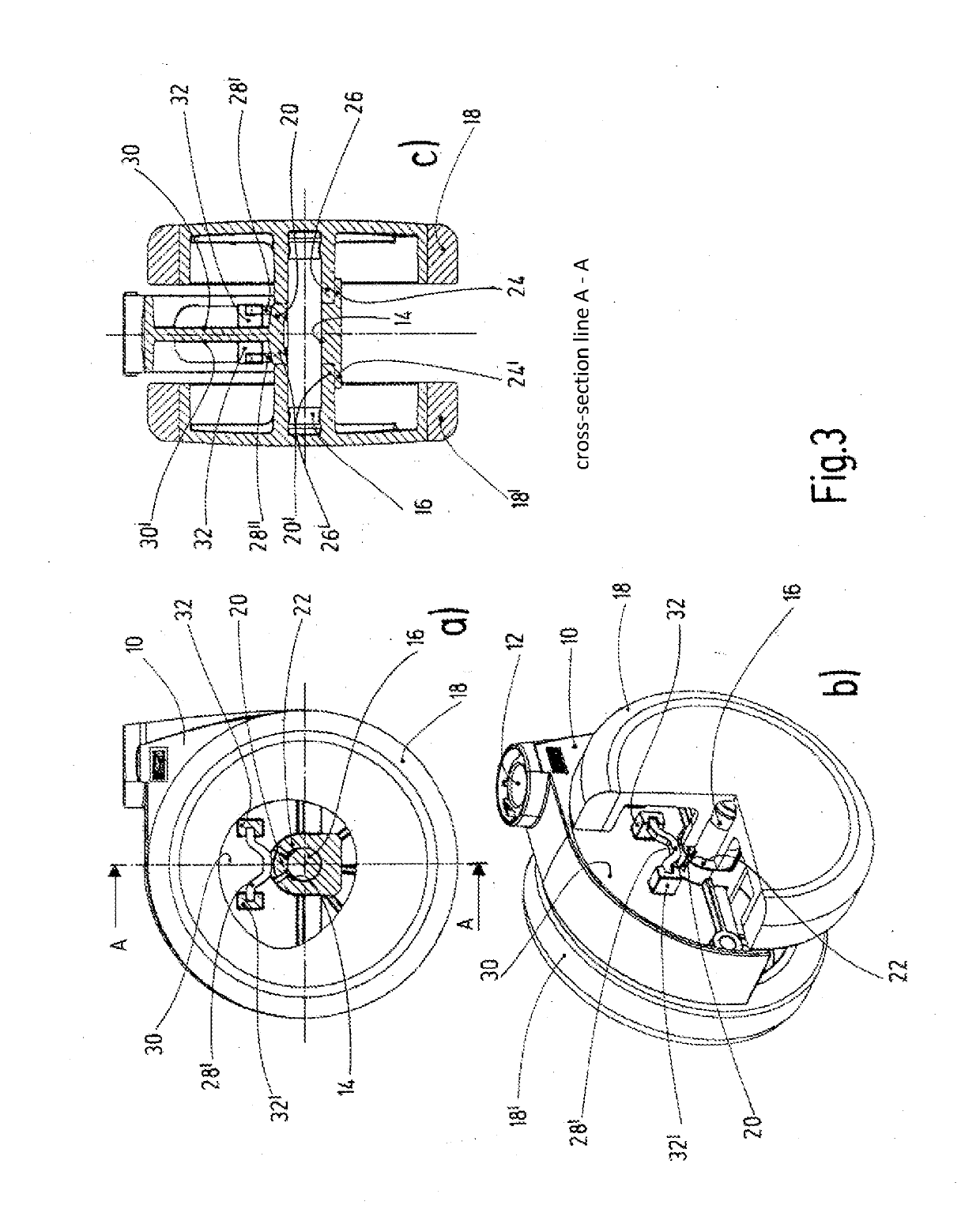
[0030]The caster shown in FIGS. 1 and 2 is designed as a double caster, and comprises a housing 10 with, at the top, a substantially vertical pin opening 12 for receiving a pivot pin to connect the caster with a piece of furniture, a housing opening 14 oriented substantially horizontally, for receiving an axle pin 16, and two wheels 18, 18′, each attached to one end of the axle pin 16. The housing opening 14 is formed as an elongated hole, in such a manner that the axle pin 16 is accommodated in the housing opening 14 in a manner allowing limited vertical displacement. It has no significant play otherwise, such that the axle pin 16 is seated in the housing opening 14 in a manner preventing wobbling.

[0031]The caster has a braking device which exerts a braking force on the wheels 18, 18′ in the unloaded state of the caster (FIG. 1) and releases the wheels 18, 18′ in the loaded state (FIG. 2).

[0032]The braking device comprises resilient housing portions 20, 20′ which are formed by slot...


PUM

PropertyMeasurementUnit
braking forceaaaaaaaaaa
resilientaaaaaaaaaa
mechanical load capacityaaaaaaaaaa

Abstract

The present disclosure relates to a caster, having a housing, having an axle pin which is arranged in a housing opening which is oriented substantially horizontally, and on which at least one wheel is mounted, having, at the top, a pin opening oriented substantially vertically, for receiving a pivot pin, and having a braking device which brakes the at least one wheel, wherein the housing opening for the axle pin allows limited vertical displaceability of the axle pin and the braking device comprises at least one resilient housing part which acts on the axle pin. In order to provide a mechanically reliable braking device, the braking device is additionally provided with at least one spring element which cooperates with the at least one resilient housing part and amplifies the effect of its braking force and / or increases the mechanical load-bearing capacity of the at least one resilient housing part.

Description

RELATED APPLICATIONS[0001]This application claims priority to German Patent Application No. 10 2016 123 080.4, filed Nov. 30, 2016, and PCT / EP2017 / 080789, filed Nov. 29, 2017, the entire contents of which are incorporated herein by reference in their entirety.FIELD[0002]The present disclosure relates to a caster having a braking device and a resilient housing.BACKGROUND[0003]The present disclosure relates to a caster, having a housing, having an axle pin which is arranged in a housing opening which is oriented substantially horizontally, and on which at least one wheel is mounted, having, at the top, a pin opening oriented substantially vertically, for accommodating a pivot pin, and having a braking device which brakes the at least one wheel in a first load state and releases the wheel in a second load state, wherein the housing opening for the axle pin allows a limited ability of the axle pin to be displaced vertically, and the braking device comprises at least one resilient housin...

Claims


Application Information

Patent Timeline
Patent Type & Authority Applications(United States)
IPC IPC(8): B60B33/00
CPCB60B33/0042B60B2360/10B60B2900/112B60B2360/102B60B33/0057B60B2360/341B60B33/0049B60B33/0073B60B2360/322B60B33/0068B60B2900/325B60B33/0078B60B2360/32B60B2200/222B60B33/0084B60B33/0094B60B2900/321
Inventor ROTTENAU, HANS-WILHELMVON BORDELIUS, RALPH
Owner GROSS FROELICH
Why Eureka
Try Eureka