UV light illuminated surgical covering apparatus and method

a surgical covering and illumination technology, applied in lighting and heating apparatus, mechanical control devices, instruments, etc., can solve the problems of wrong device activation, significant patient and surgeon harm, wrong pedal depressing, etc., to reduce surgeons, maintain clean surgical environment, and easy identification

Active Publication Date: 2019-10-24
FACULTY PHYSICIANS & SURGEONS OF LOMA LINDA UNIV SCHOOL OF MEDICINE
View PDF3 Cites 0 Cited by
  • Summary
  • Abstract
  • Description
  • Claims
  • Application Information

AI Technical Summary

Benefits of technology

[0009]To reduce surgeon or other user error, the foot pedal may be provided with an embodiment of an illuminated cover including an optically brightened layer that, when illuminated, allows the surgeon or other user to easily identify the appropriate foot pedal to be used. For example, objects or materials having an optically brightened exterior may fluoresce when exposed to ultraviolet (UV) light, and an example of such a UV light may be what is known as a blacklight. In some embodiments, this optically brightened exterior may include a white exterior, though other colors may also be optically brightened so as to fluoresce responsive to activation of UV light. In some embodiments, this optically brightened layer may include an optically brightened material layer, or in other embodiments may include an optically brightened coating. In embodiments where the optically brightened layer includes an optically brightened material layer, the optically brightened material layer may include an illuminated protective cover that may also protect the foot pedal from moisture damage as well as debris generated from the environment, such as during a surgical procedure. In some embodiments, the foot pedal and / or the optically brightened material layer or coating may be color-coded to help the surgeon or other user identify the purpose of each pedal as well as the proper placement of the foot. In some embodiments, a foot pedal may have a number of different actuators (e.g., pedals, buttons, etc.). The illuminated cover may help the surgeon or other user identify the location of each of the different actuators.
[0010]The illumination devices and illuminated cover may be separately attached such that the surgeon may easily adapt the illuminated cover for any device being used with a foot pedal. Further, the illumination devices and / or the illuminated cover may be disposable and configured to be used on a foot pedal of any size or shape. Disposability, for example, may be important for maintaining a clean surgical environment.
[0011]In some embodiments, the illuminated cover may further include a frame to provide additional protection to the foot pedal and for elevated lighting of the foot pedal. The illuminated cover may also include an attachable friction surface to prevent the covered foot pedal from slipping against a surface.

Problems solved by technology

Furthermore, many surgical procedures, such as those involving endoscopy, laparoscopy, and robotic devices, as well as other, non-surgical uses of foot pedals, can require a darkened environment or areas with low light.
The darkened environment and the location of the foot pedals create a situation that can result in human error as the inability to easily and properly locate the proper foot pedal can cause the wrong pedal to be depressed and the wrong device to be activated.
In surgical contexts, operating the wrong foot pedal can result in significant patient and surgeon harm.
As well, the darkened environment can cause the user to have difficulty locating the foot pedal, which can lead to missing or kicking of the foot pedal.

Method used


Image

  • UV light illuminated surgical covering apparatus and method
  • UV light illuminated surgical covering apparatus and method
  • UV light illuminated surgical covering apparatus and method

Examples


Embodiment Construction

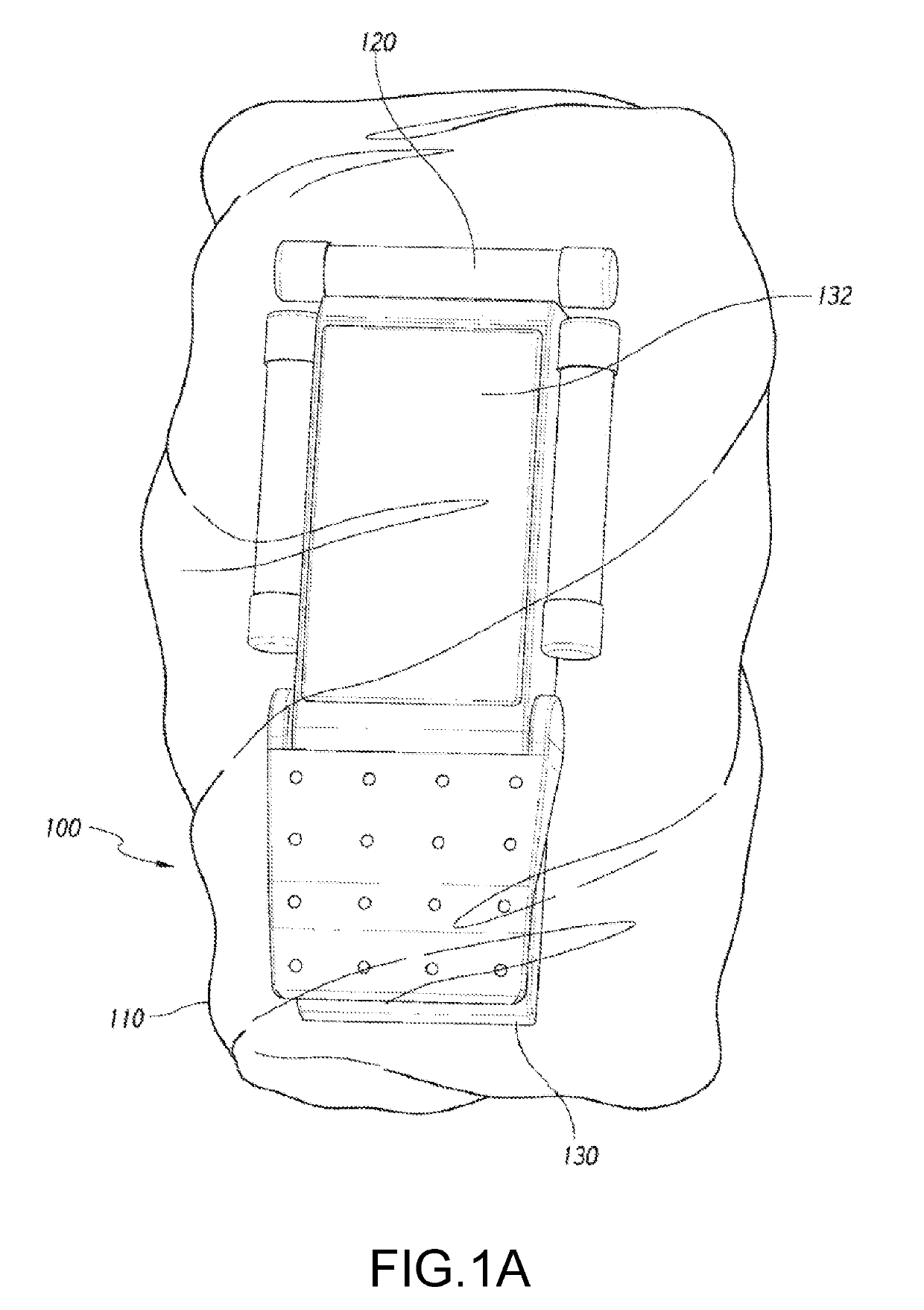
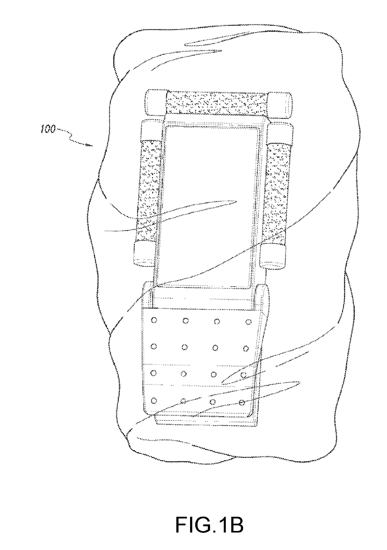
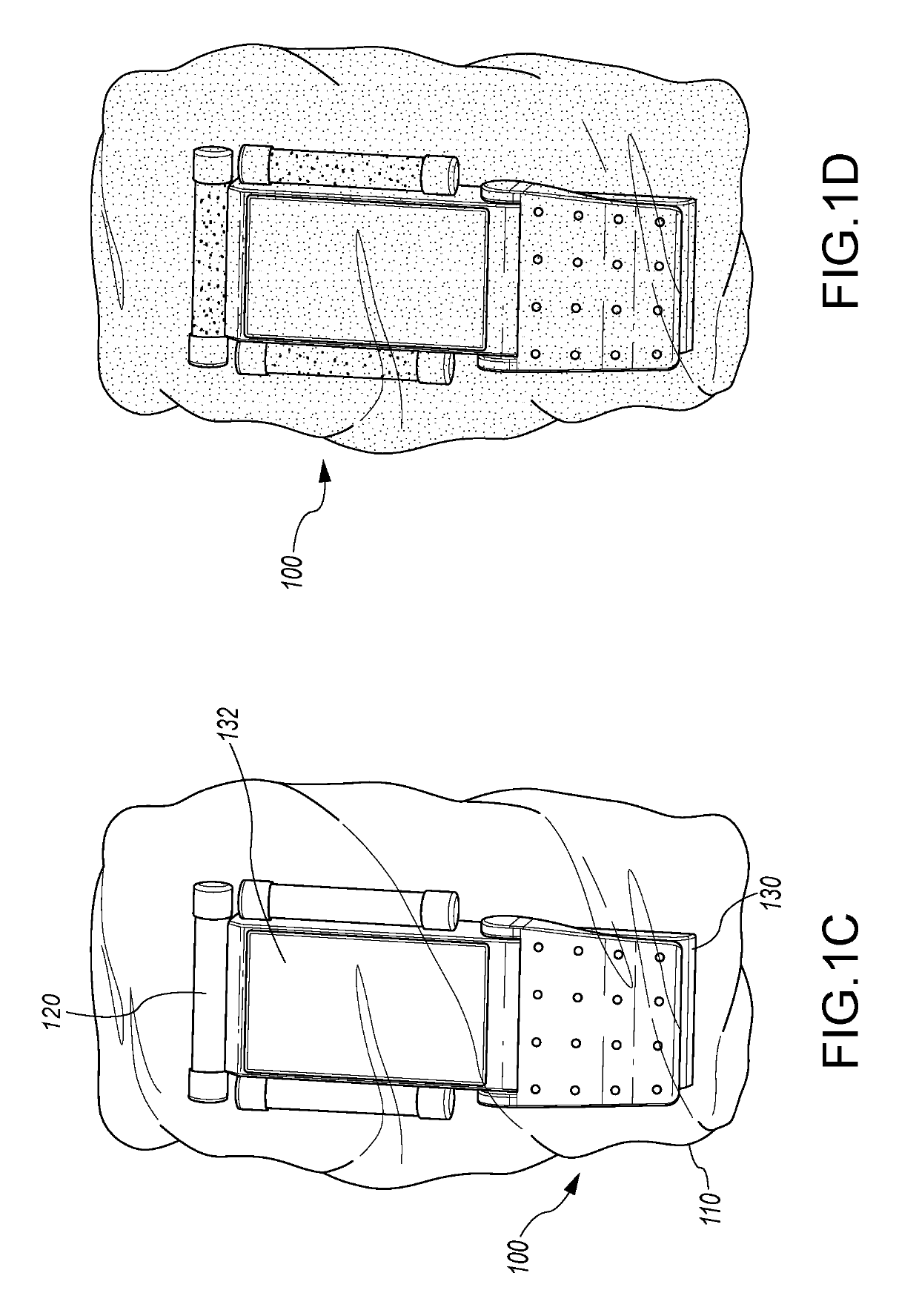
[0046]Various illuminated device covers, assemblies, and methods are disclosed to illustrate various examples that may be employed to achieve one or more desired improvements. For purposes of presentation, certain embodiments are disclosed with respect to a surgical device with a foot pedal, but the disclosed invention may be used in other contexts as well. Indeed, the described embodiments are examples only and are not intended to restrict the general disclosure presented and the various aspects and features of this disclosure. The general principles described herein may be applied to embodiments and applications other than those discussed herein without departing from the spirit and scope of the disclosure. This disclosure should be afforded the widest scope consistent with the principles and features that are disclosed or suggested herein.

[0047]Although certain aspects, advantages, and features are described herein, it is not necessary that any particular embodiment include or ac...


PUM


Abstract

A system and method of illuminating one or more foot pedals with an optically brightened layer positioned to fluoresce responsive to activation of one or more ultraviolet (UV) illuminating devices positioned adjacent or attached to the one or more foot pedals. The optically brightened layer may include an optically brightened coating covering at least a portion of each of the one or more foot pedals, or may include an optically brightened material layer positioned to cover and protect each of the one or more foot pedals from debris or moisture during use. A friction portion may be attached to the optically brightened material layer, the friction portion being positioned adjacent a lower surface of the foot pedal when the optically brightened material layer surrounds the foot pedal, the friction portion being configured to prevent sliding of the foot pedal against the floor or other surface.

Description

INCORPORATION BY REFERENCE TO ANY PRIORITY APPLICATIONS[0001]The present application is a Continuation in Part of and claims priority to and benefit of U.S. Non-Provisional application Ser. No. 16 / 048,260, titled “ILLUMINATED PROTECTIVE COVERING FOR FOOT PEDALS,” filed Jul. 28, 2018, which is a Continuation of U.S. Non-Provisional application Ser. No. 15 / 592,907, titled “ILLUMINATED PROTECTIVE COVERING FOR FOOT PEDALS,” filed May 11, 2017, which is a Continuation in Part of International Application No. PCT / US2015 / 061523, titled “ILLUMINATED PROTECTIVE COVERING,” filed Nov. 19, 2015, which claims priority to and the benefit of U.S. Provisional Application No. 62 / 083,098, titled “FOOT PEDAL LIGHTS,” filed Nov. 21, 2014; the full disclosure of each of these preceding applications is incorporated herein by reference in its entirety. U.S. Non-Provisional application Ser. No. 15 / 592,907, titled “ILLUMINATED PROTECTIVE COVERING FOR FOOT PEDALS,” filed May 11, 2017, also claims priority to...

Claims


Application Information

Patent Timeline
Patent Type & Authority Applications(United States)
IPC IPC(8): F21V33/00G05G1/44A61B46/10F21V31/00G05G1/30G05G25/04F21V23/04F21V3/04
CPCF21V3/04A61B18/00A61B2017/00973G05G25/04F21V33/0068A61B46/10A61B2017/00907F21V31/00G05G1/30G05G1/44F21V23/04F21W2131/20A61B34/30A61B34/74A61B2017/00876A61B46/40A61B90/92A61B2090/304H01H9/182H01H9/185H01H3/14
Inventor BALDWIN, DALTON DUANESAMARDZIJA, MICHAEL R.ZIVANOVIC, ZORAN
Owner FACULTY PHYSICIANS & SURGEONS OF LOMA LINDA UNIV SCHOOL OF MEDICINE
Why Eureka
Try Eureka