Unlock instant, AI-driven research and patent intelligence for your innovation.

Switching device

a switching device and contact technology, applied in the direction of electric switches, contact driving mechanisms, electric switches, etc., can solve the problems of reducing the clearance angle is not large, and the contact angle is relatively small, so as to reduce the size of the switch assembly

Active Publication Date: 2019-10-24
ABB OY
View PDF2 Cites 2 Cited by
  • Summary
  • Abstract
  • Description
  • Claims
  • Application Information

AI Technical Summary

Benefits of technology

The switching device has the advantage of having a large angle between the positions of the switch when it is turned on and off. This allows for a smaller size of the device compared to one with a smaller angle.

Problems solved by technology

One of the problems associated with the above mentioned known switching device is that a clearance angle between positions of a roll element corresponding to an ON-state and an OFF-state of switch contacts is relatively small, approximately 45°.

Method used


Image

  • Switching device
  • Switching device
  • Switching device

Examples


Embodiment Construction

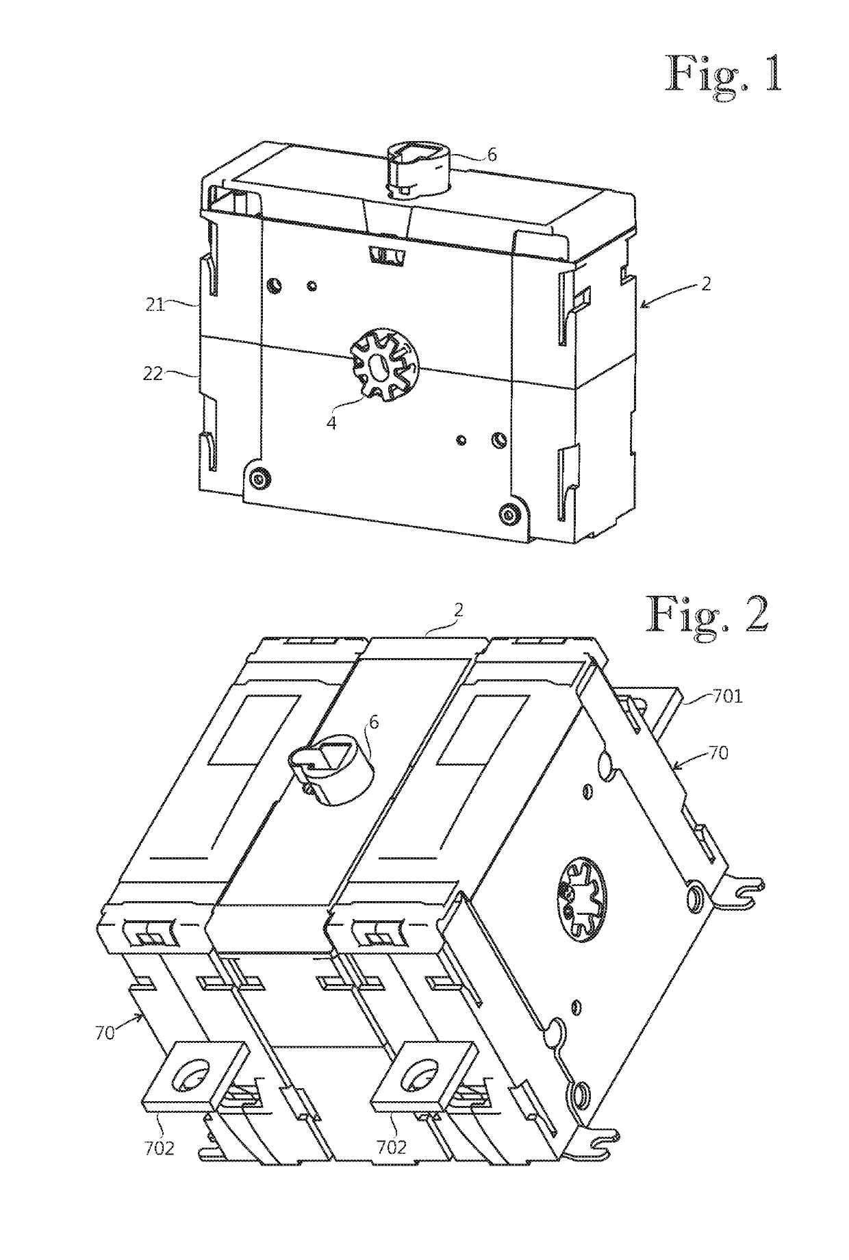
[0016]FIG. 1 shows a switching device comprising a frame 2, a roll element 4 rotatable between a first position and a second position relative to the frame 2, a control shaft 6 rotatable between an ON-position and an OFF-position relative to the frame 2, and a drive system. The roll element 4 is adapted to transfer from the first position to the second position in an opening event for transferring a switch contact system from an ON-state to an OFF-state. The control shaft 6 is adapted to control rotation of the roll element 4 such that rotating the control shaft 6 from the ON-position to the OFF-position carries out the opening event. The drive system operationally connects the control shaft 6 to the roll element 4 for rotating the roll element 4. The control shaft 6 extends through an upper part 21 of the frame 2, and is adapted to be rotated by a user. The control shaft 6 is adapted to be connected to an operating handle (not shown) which is adapted to be operated by the user.

[001...


PUM


Abstract

A switching device including a frame, a roll element, a control shaft, a drive system and a roll spring. The control shaft is adapted to control rotation of the roll element such that rotating the control shaft from an ON-position to an OFF-position carries out an opening event in which the roll element transfers from a first position to a second position. The drive system includes an actuator and an actuator spring. The drive system is adapted to rotate the roll element during the opening event to an intermediate position located between the first position and the second position. The roll spring is connected between the frame and the roll element, and is adapted to rotate the roll element to the second position during the opening event.

Description

FIELD OF THE INVENTION[0001]The present invention relates to a switching device.[0002]An example of a known switching device is described in publication EP1719142.[0003]One of the problems associated with the above mentioned known switching device is that a clearance angle between positions of a roll element corresponding to an ON-state and an OFF-state of switch contacts is relatively small, approximately 45°.BRIEF DESCRIPTION OF THE INVENTION[0004]An object of the present invention is to provide a switching device so as to solve the above problem. The objects of the invention are achieved by a switching device which is characterized by what is stated in the independent claim. The preferred embodiments of the invention are disclosed in the dependent claims.[0005]The invention is based on the idea of providing a switching device with at least one roll spring connected between a frame of the switching device and a roll element of the switching device, the at least one roll spring bei...

Claims


Application Information

Patent Timeline
IPC IPC(8): H01H19/24
CPCH01H19/24H01H2235/01H01H19/08H01H19/14H01H3/40H01H3/42H01H19/20
Inventor STRAND, FREDRIK
Owner ABB OY