
Combination luggage and child carrier

Active Publication Date: 2019-10-31
TRAVEL GLIDER IP PTY LTD AS TRUSTEE FOR TRAVEL GLIDER IP UNIT TRUST
View PDF0 Cites 4 Cited by
  • Summary
  • Abstract
  • Description
  • Claims
  • Application Information

AI Technical Summary

Benefits of technology

The patent is about a child seat that can be used with a luggage apparatus. The seat is independent of the handle, which can be pushed from the front or rear in different configurations. This makes it easier to face the infant while transporting them. The seat can also be used as a child seat when not using the luggage apparatus by simply leaving the handle in its stowed position. The seat can be made lighter and more comfortable by using a lightweight, breathable material and adjusting the angle of recline for the child. These features reduce weight, parts, and make the recline adjustment system simpler.

Problems solved by technology

It is well known that carers of infants and young children experience difficulties when travelling on aircraft.
However, travelers with young children may need to carry the children as well as pulling or pushing wheeled luggage.
Especially in the case of a single traveler it can be very burdensome to transport the carry-on luggage and carry a child or infant.
A child stroller can be used, but child strollers are usually large and cumbersome.
They typically do not fold down sufficiently to fit within carry-on flight luggage dimensions.
Therefore child strollers are required to be transported in the hold as oversize luggage, in some situations adding to the cost of flying.
They may also be damaged or soiled when stowed or transferred.
There is a danger of the child falling off or the luggage tipping over.
In addition, the rearwardly-projecting wheels can interfere with the traveler's stride when pushing the luggage and cause tripping.
It is necessary to have wheels on a scissor-like support member protrude rearwardly, in order to help stabilize the structure, but the wheels can present a walking hazard.
Further, the seating position for the child is high above the ground, and there is a danger that the child may fall off and injure itself or that the suitcase may topple over with the same result.
Lastly, this suitcase is relatively large and would exceed the size permitted for use as cabin luggage.
Once again, it is necessary to have wheels on a scissor-like support member protrude rearwardly, in order to help stabilize the structure, but the wheels can present a walking hazard.
In addition, the seating position for the child is high above the ground, and there is a danger that the child may fall off and injure itself or that the cabin bag may topple over with the same result.
Some solutions reduce the storage capacity of the luggage.
The prior art does not cater for the carriage of infants, who need to be transported in a reclining position for the infant's safety, preferably at an angle of less than 40 degrees to the horizontal.
Further, the prior art does not provide a luggage apparatus versatile enough to transport an infant at first and later the growing child.

Method used


Image

  • Combination luggage and child carrier
  • Combination luggage and child carrier
  • Combination luggage and child carrier

Examples


second embodiment

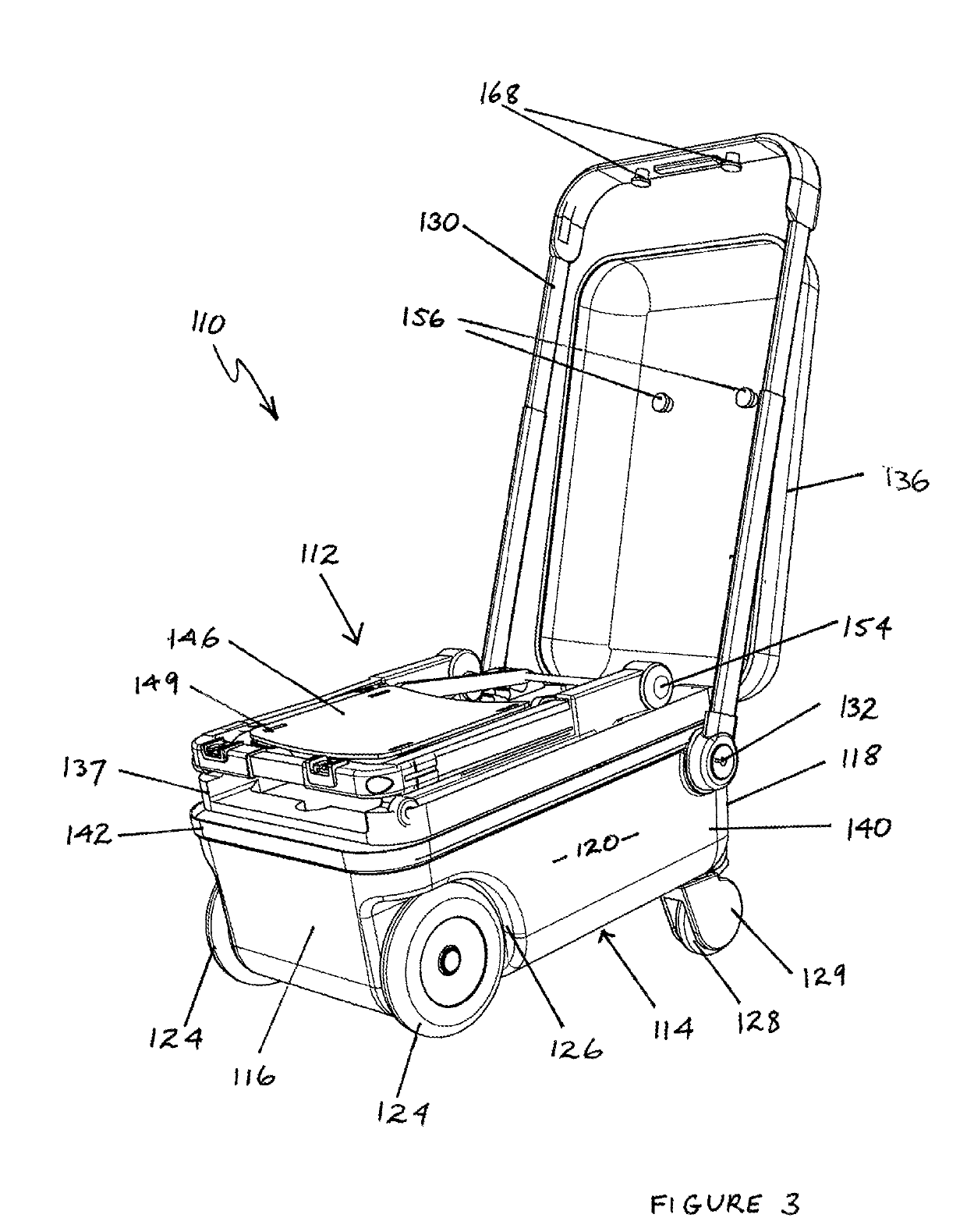
[0081]Turning now to the second embodiment in FIGS. 3 to 7, luggage apparatus 110 has hard shell panels and has a top 112, a bottom 114, a front 116, a rear 118 and side 120. The opposing side to side 120 is not visible in the Figures but is parallel to side 120. For convenience below, the opposing side will be referred to as side 122, although not labelled in the Figures. The distance between front 116 and rear 118 is longer than the distance between opposing sides 120 and 122.

[0082]First wheels means 124 are located at front 116, in recesses 126, only one of which is visible in FIGS. 3 to 6. Wheels 124 are aligned with opposing sides 120 and 122 and are used to enable wheeling of luggage apparatus 110 in normal mode, when luggage apparatus 110 is transported with front 116 being closest to the ground.

first embodiment

[0083]Second wheels 128 in wheel assembly 129 are located at each side of rear 118 and are swiveling castor wheels, as in the

[0084]Handle 130 pivots at pivot points 132 to lie around opposing sides 120 and 122 and front 116 when luggage 110 is in the normal mode and is to be carried. Alternately, handle 130 may be used to pull or push luggage apparatus 110 in the normal mode, by pivoting handle 130 at pivot points 132. Handle 130 can be extended or contracted telescopically. In FIGS. 3 to 7, handle 30 is shown, unextended, in child carrying mode.

[0085]In this embodiment, luggage apparatus 110 has a first compartment formed between closure 136 and support 137. Closure 136 extends the length of luggage apparatus 110, between front 116 and rear 118 and has a hinge (not shown) attaching closure 136 to luggage apparatus 110 at rear 118. Closure 136 can be latched at front 116 and / or at sides 120, 122 in the desired manner, when luggage apparatus 110 is used in normal mode.

[0086]Luggage a...


PUM


Abstract

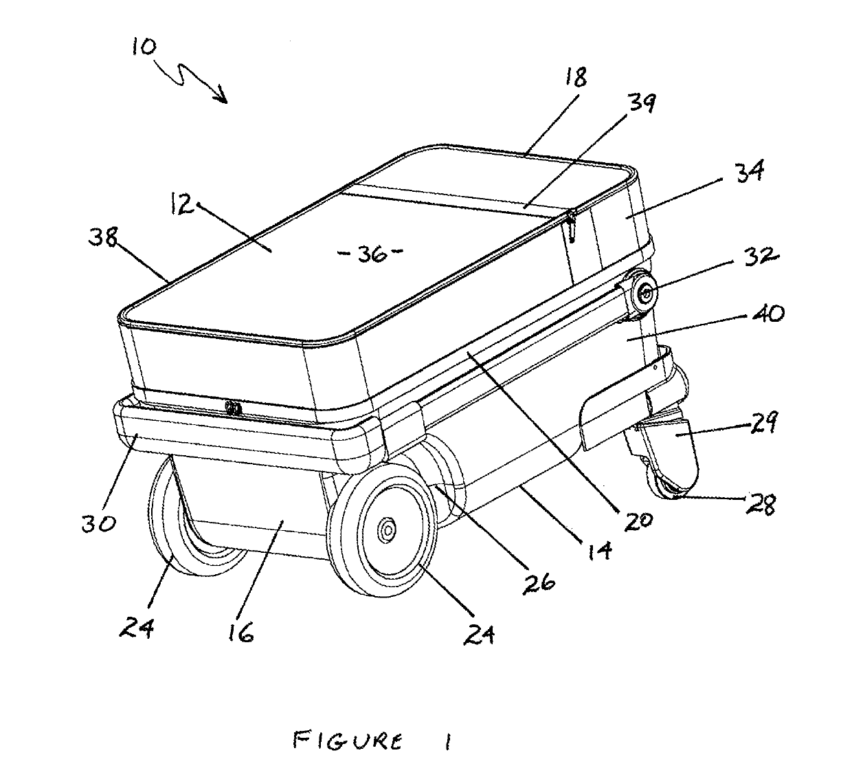
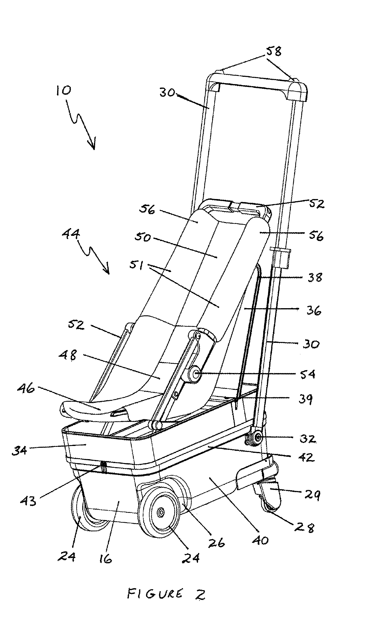
The invention provides a luggage apparatus (10, 110) capable of being used in normal mode and alternately in child carrying mode. Luggage apparatus (10, 110) has a top (12, 112) a bottom (14, 114), a front (16, 116), a rear (18, 118) and opposing sides (20, 120) and (22, 122). The dimension between the front (16, 116) and the rear (18, 118) is longer than the dimension between the opposing sides (20, 120) and (22, 122). A first wheel means (24, 124) is located in the vicinity of the front (16, 116). The first wheel means (24, 124) is used to wheel luggage apparatus (10, 110) in normal mode. A second wheel means (28, 128) is located in the vicinity of the rear (18, 118) and, in conjunction with the first wheel means (24, 124), can be used to wheel the luggage apparatus (10, 110) in child carrying mode. A child seat (44, 144) is foldable within the luggage apparatus (10, 110) in normal mode and unfoldable in child carrying mode to be positioned on or above the top (12, 112) of the luggage apparatus (10, 110). In child carrying mode, the longer dimension is substantially parallel to the ground supporting the luggage apparatus (10, 110) and the unfolded child seat (44, 144) is positioned so that the centre of gravity of the child seat (44, 144) and any child thereon is substantially between the front (16, 116) and the rear (18, 118).

Description

PRIORITY[0001]Priority is claimed of Australia patent application No 2016904228, the contents of the disclosure in which are incorporated herein by reference.FIELD[0002]The present invention relates to a luggage apparatus capable of being used as a child carrier. In some embodiments, the invention provides a luggage apparatus which is light enough to qualify as cabin luggage or carry-on luggage for an aircraft but which is able to transport an infant or child outside the aircraft.BACKGROUND[0003]The following references to and descriptions of prior proposals or products are not intended to be, and are not to be construed as, statements or admissions of common general knowledge in the art. In particular, the following prior art discussion does not relate to what is commonly or well known by the person skilled in the art, but assists in the understanding of the inventive step of the present invention, of which the identification of pertinent prior art proposals is but one part.[0004]I...

Claims


Application Information

Patent Timeline
IPC IPC(8): A45C5/14B62B3/02
CPCA45C5/14A45C2009/002B62B3/02B62B2205/04A45C2005/037B62B5/082A45C5/03A45C5/146A45C9/00B62B2202/24B62B2205/14A45C2005/148
Inventor NEWMAN, BENJAMIN JOHN
Owner TRAVEL GLIDER IP PTY LTD AS TRUSTEE FOR TRAVEL GLIDER IP UNIT TRUST
Learn More