
Below structural obstruction fire sprinkler installation method and heat collector system

a technology of installation method and heat collector, which is applied in fire rescue, spray nozzles, spraying apparatus, etc., can solve the problems of accidental ignition, increased risk of failure to pass inspection, and increased risk of legal liability, so as to reduce the risk of fire, less water, and less pressure to combat fire.

Inactive Publication Date: 2019-10-31
FIREBIRD SPRINKLER COMPANY
View PDF2 Cites 4 Cited by
  • Summary
  • Abstract
  • Description
  • Claims
  • Application Information

AI Technical Summary

Benefits of technology

This patent invention is about a new way to install sprinkler heads in building structures. The invention is to place the sprinkler heads below the bottom chords of all metallic structural support members. This has several advantages. First, it prevents the sprinkler heads from being obstructed by the trusses or I-beams, which could interfere with their spray pattern.Second, the heat from fires can be used to deflect the sprinkler heads off the obstacles, which can trigger them. By installing the sprinkler heads in this way, they become less obstructive, which means that less water and pressure are needed to fight fires, resulting in savings in materials and labor.

Problems solved by technology

In many cases, the commercial value of items (including people and / or animals) contained within a warehouse can often be many times greater than the cost of the warehouse itself.
Sparks from forklift trucks and dropped cigarettes are common sources of accidental ignition.
These and other factors make warehouses a special challenge for fire fighters.
Installers of prior art fire suppressions systems must follow the rules or risk failure to pass inspections and / or expose to legal liability.
It is of course time-consuming and cumbersome to locate supply lines through / around the metallic structural support members, while avoiding obstacles like HVAC ductwork and electrical lines that are also commonly tucked in-between the metallic structural support members.
In addition to increased installation difficulty and costs, the prior art practice of locating sprinkler heads A twelve-to-eighteen inches (12-18 in.) from the ceiling deck also results in significant disturbance of the emitted water spray patterns in warehouse applications.
Prior art sprinkler heads A that are tucked in-between the metallic structural support members near the ceiling deck must spray through and around obstacles (including HVAC ductwork), which causes serious disruption of the intended water spray geometry D and uneven wetting over the intended coverage areas.
Another issue concerns water density.
Large clearances between and floor-level combustibles could mean that the correct water density is not delivered to a fire.
In practice, however, heat collectors have been largely disfavored in the fire protection industry.
One reason is that heat collectors tend to produce a dead air space—especially bell-shaped heat collectors.
Another reported problem with heat collectors has been that they are only effective when located directly within the fire plume B. Some studies have suggested that sprinkler heads A equipped with heat collector devices that were located outside the plume B sometimes did not respond at all because the heat collector would deflect the convective heat flow of the ceiling jet C. That is, there is some evidence to suggest, counterintuitively, that a prior art heat collector may even delay activation because it traps a bubble of cool dead air below and prevents the ceiling jet from reaching the sprinkler from above.

Method used


Image

  • Below structural obstruction fire sprinkler installation method and heat collector system
  • Below structural obstruction fire sprinkler installation method and heat collector system
  • Below structural obstruction fire sprinkler installation method and heat collector system

Examples


Embodiment Construction

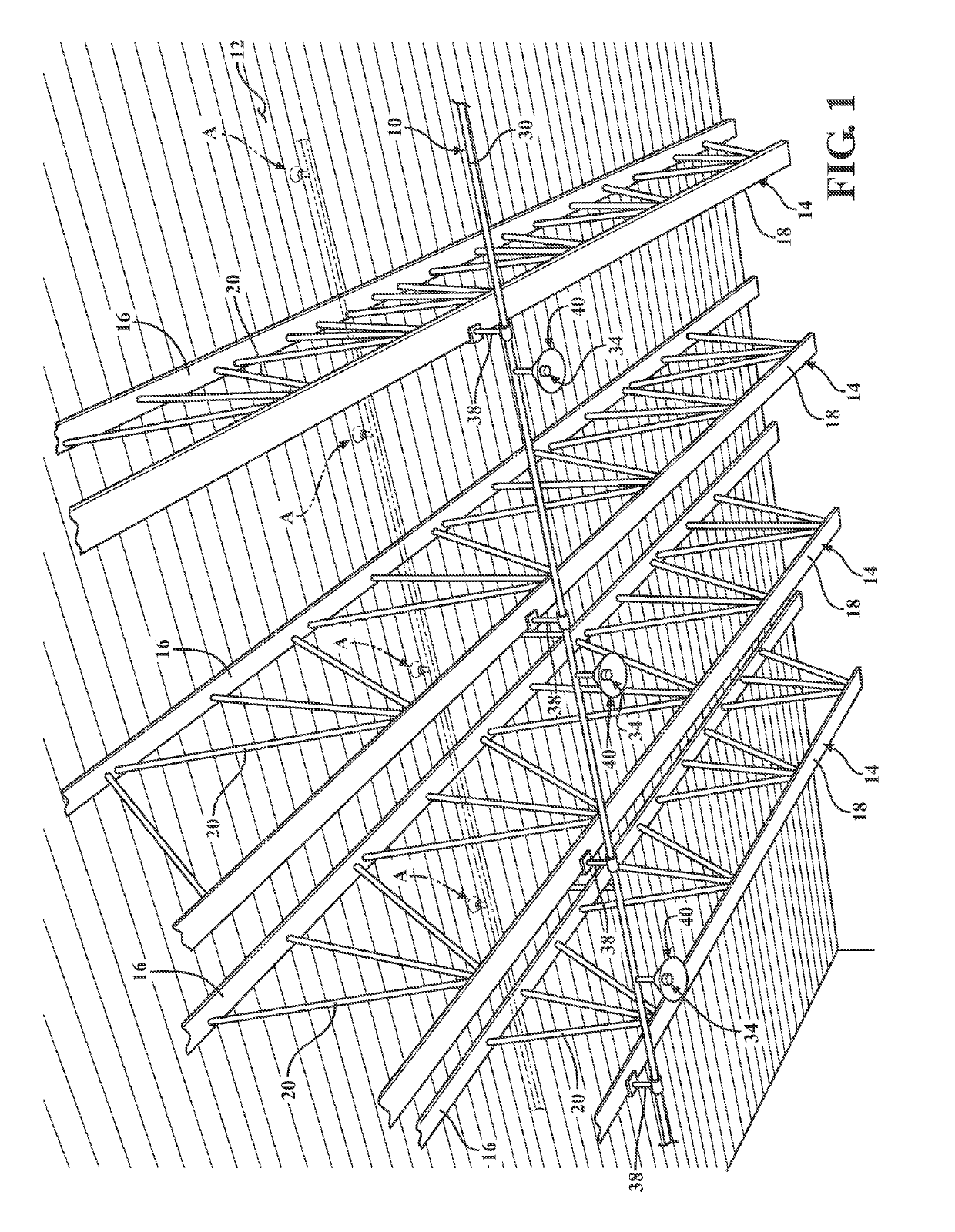
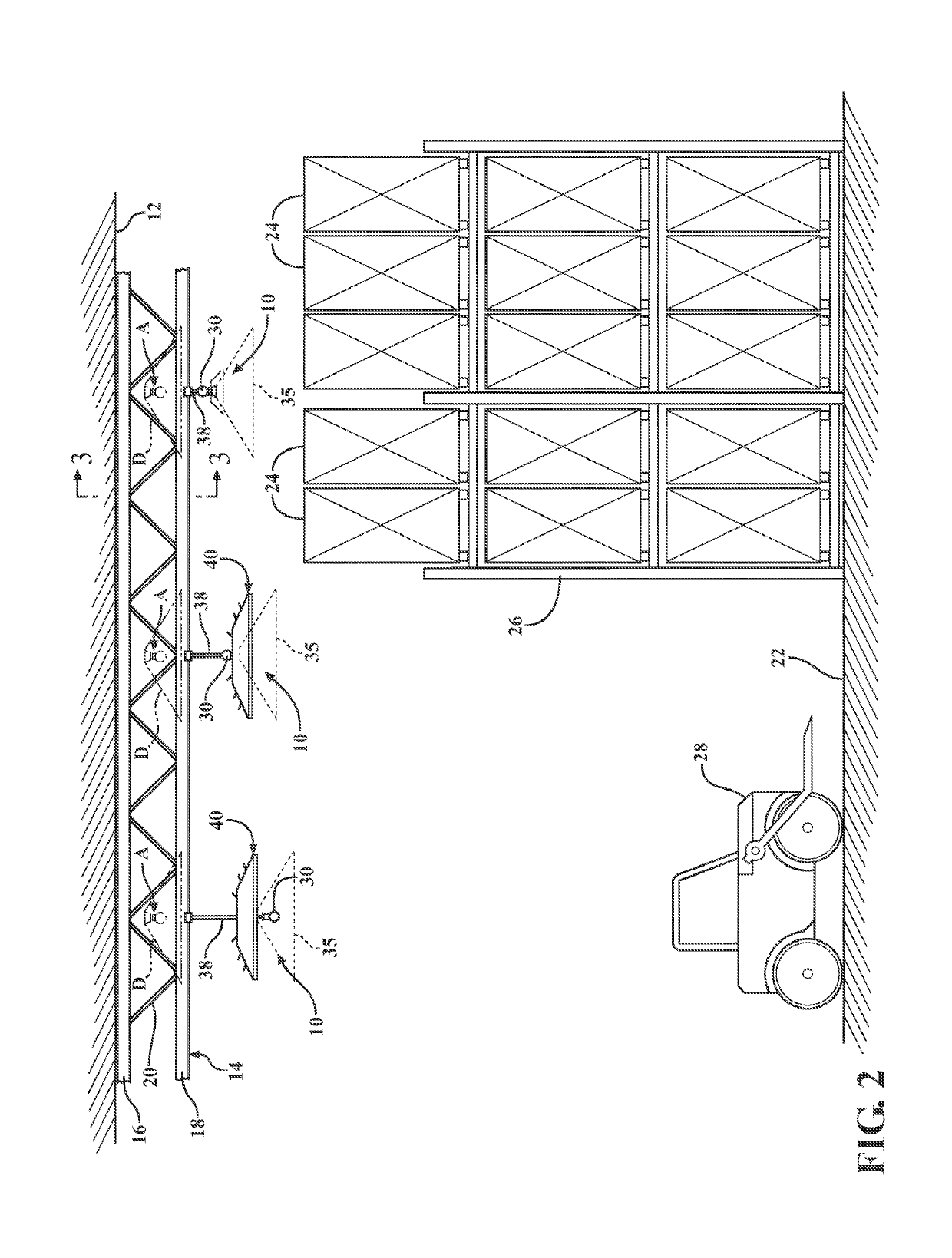
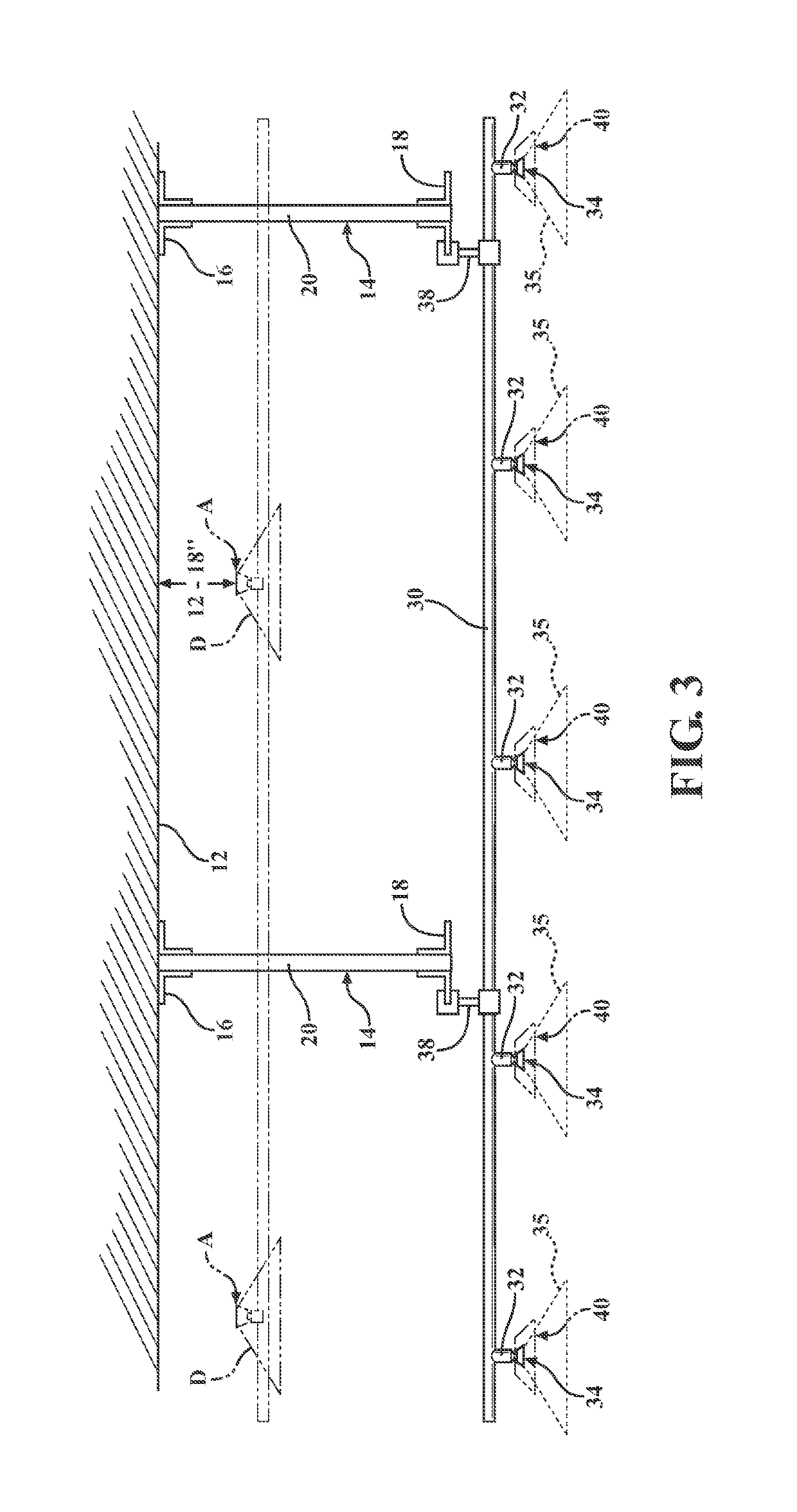
[0028]Referring to the figures, wherein like numerals indicate like or corresponding parts throughout the several views, a fire suppression system according to one exemplary expression of the present invention is generally shown at 10 in FIGS. 1-3. The fire suppression system 10 is depicted in combination with warehouse of the type having a ceiling deck 12 covering a storage area. A plurality of metallic structural support members 14 uphold the ceiling deck 12. Although some aspects and features of the present invention may be usefully applied in the context of wooden support beams, the core novel concepts of this present invention are best exploited in combination with metallic structural support members 14.

[0029]To reiterate, building structures sheltering a large area and which have a high ceiling deck 12 supported by metallic structural support members 14 can be put to many different uses. One common application is as a storage facility for storing large quantities of commercial...


PUM


Abstract

A fire suppression system specially adapted for placement in a warehouse having a ceiling deck supported by exposed metallic structural support members. The fire suppression system includes a supply line that feeds water to an array of self-activating sprinkler heads. The sprinkler heads are located near or below the exposed metallic structural support members to achieve many performance-enhancing and cost-saving benefits. One or more sprinkler heads may include respective heat collectors designed to capture upwardly rising heat plumes. The heat collectors agitate the collected air to improve activation responsiveness. In some embodiments, the heat collectors include vent-like aspiration ports coupled with exterior louvers to scavenge heat from a ceiling jet.

Description

CROSS REFERENCE TO RELATED APPLICATIONS[0001]This application is a Continuation-in-Part of U.S. application Ser. No. 16 / 208,649 filed Dec. 4, 2018, which is a Continuation-in-Part of U.S. application Ser. No. 15 / 598,808 filed May 18, 2017, which is a Continuation-in-Part of U.S. application Ser. No. 15 / 257,961 filed Sep. 7, 2016, which claims priority to Provisional Patent Application No. 62 / 215,058 filed Sep. 7, 2015, and is a Continuation-in-Part of U.S. application Ser. No. 14 / 661,302 filed Mar. 18, 2015, which claims priority to Provisional Patent Application No. 62 / 019,527 filed Jul. 1, 2014 and to Provisional Patent Application No. 61 / 955,253 filed Mar. 19, 2014, and this application also claims priority to Provisional Patent Application No. 62 / 697,009 filed Jul. 12, 2018, the entire disclosures of which are hereby incorporated by reference and relied upon.BACKGROUND OF THE INVENTION[0002]Certain kinds of building structures are very large with relatively high ceiling decks th...

Claims


Application Information

Patent Timeline
Patent Type & Authority Applications(United States)
IPC IPC(8): A62C35/68A62C37/12A62C31/02A62C3/00A62C37/11A62C35/64B05B1/26
CPCA62C37/12A62C31/02B05B1/267A62C35/68A62C3/002A62C35/64A62C37/11A62C35/60
Inventor PIGEON, JEFFREY J.
Owner FIREBIRD SPRINKLER COMPANY
Learn More