Eureka AIR delivers breakthrough ideas for toughest innovation challenges, trusted by R&D personnel around the world.

Roof edge ladder guard

a technology for roof edges and ladders, applied in ladders, building construction, construction, etc., to achieve the effect of easy nailing or screwing to the roof, easy carrying up a ladder, and convenient positioning

Active Publication Date: 2019-10-31
JAMES JR HARLEY D
View PDF34 Cites 6 Cited by
  • Summary
  • Abstract
  • Description
  • Claims
  • Application Information

AI Technical Summary

Benefits of technology

The present invention is a ladder safety device that can be easily carried up a ladder and installed on an existing roof. It is designed to secure the ladder to the roof and provide a safe layer of protection for the roof. The device can be easily installed and removed with the ladder.

Problems solved by technology

Difficulties with using ladder safety devices of the types above include carrying the materials or plates up a ladder, and maneuvering them under existing shingles or other roof coverings and holding them in place while nailing or screwing them to the roof—especially since the ladder is unsecured during the installation.

Method used


Image

  • Roof edge ladder guard
  • Roof edge ladder guard
  • Roof edge ladder guard

Examples


Embodiment Construction

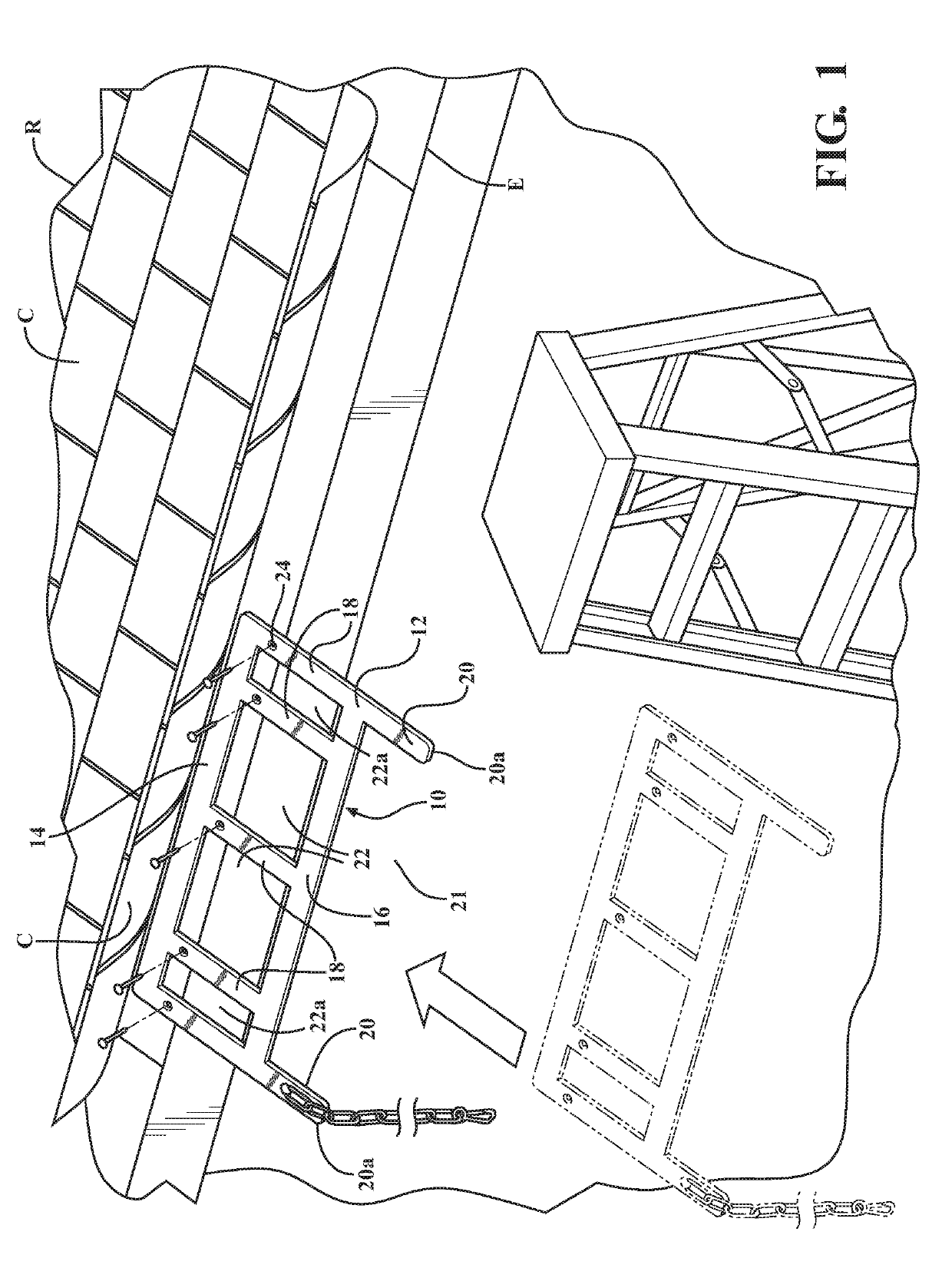
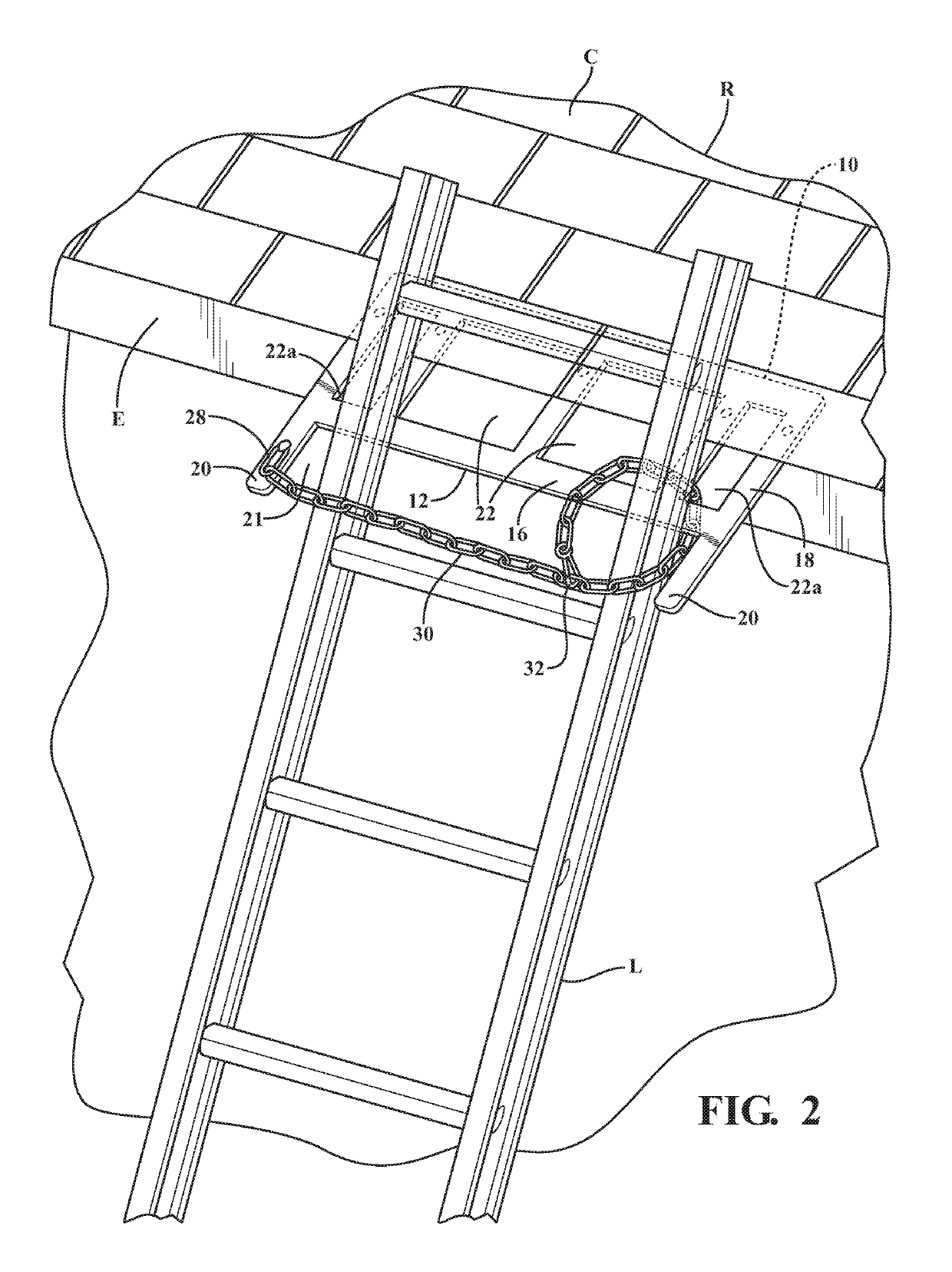
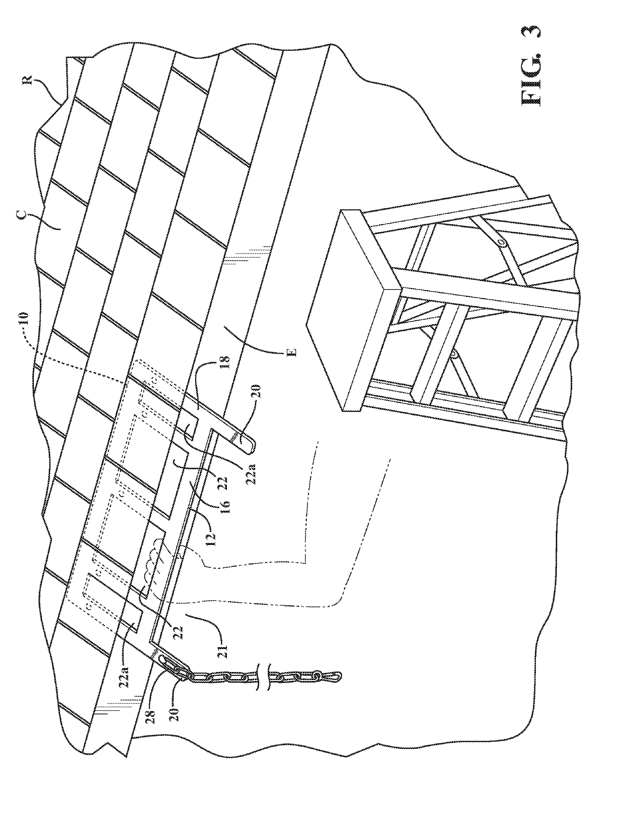
[0020]Referring first to FIG. 1, a ladder safety device 10 according to the invention is shown in exemplary form in order to teach how to make and use the claimed invention. Ladder safety device 10 comprises a generally flat, planar body 12 made from a rigid, durable material such as steel, aluminum, or high-strength plastic. Body 12 is formed from a plurality of flat, spaced rail members that define a plurality of relatively large hand-grip openings between them.

[0021]In the illustrated example, body 12 includes a horizontal inner rail 14, a horizontal outer rail 16 spaced from and generally parallel to inner rail 14, and a plurality of vertical rails 18 generally perpendicular to and joining the horizontal inner and outer rails 14, 16 into a single rigid body. “Horizontal” and “vertical” are used herein as convenient shorthand for the relative alignment of the rails in the plane of body 12, and not as precise designations of orientation relative to the ground, and further can incl...


PUM


Abstract

A ladder safety device configured to be secured to the edge of roof to prevent a ladder leaned against it from sliding sideways or falling away from the roof edge . The ladder safety device comprises a generally flat, planar inner body portion comprising a first inner horizontal rail and vertical rails spaced from one another to define a plurality of large hand-grip openings between them. The ladder safety device further includes an outer body portion comprising a second horizontal rail spaced vertically from the first horizontal rail and connected thereto by outer portions of the vertical rails. Fastener holes formed along inner ends of the vertical rails can be used to secure the device to a roof, and projecting outer fingers define a ladder recess on an outer edge of the outer body portion. The ladder safety device is installed with the outer horizontal rail and portions of the vertical rails and the hand-grip openings spaced outwardly from the roof edge to provide a hand grip.

Description

RELATED APPLICATIONS / PRIORITY BENEFIT CLAIM[0001]This application claims the benefit of U.S. Provisional Application No. 62 / 663,461 filed Apr. 27, 2018 by the same inventor (James), the entirety of which provisional application is hereby incorporated by reference.FIELD[0002]The subject matter of the present application is in the field of safety devices for temporary mounting along roof edges to prevent ladders from sliding off or falling away from the roof.BACKGROUND[0003]Ladder safety devices that provide ladder-anchoring and roof-protecting functions are known. For example, people working on the roof may temporarily nail scrap pieces of lumber to project from the roof edge to secure a ladder between them.[0004]A more structured, commercial example is shown in U.S. Pat. No. 6,722,469 to Weger, Jr., which discloses a rigid flat plate sized for installation between a roof and a roof covering, with nail holes and / or a puncturable plate material for attaching the plate to the roof, and...

Claims


Application Information

Patent Timeline
Patent Type & Authority Applications(United States)
IPC IPC(8): E06C7/48E06C7/50
CPCE06C7/48E06C7/50E06C1/04E06C7/188E06C7/488E06C7/505
Inventor JAMES, JR., HARLEY D.
Owner JAMES JR HARLEY D
Why Eureka
Eureka Blog
Learn More