Fuel Supply Device

a fuel supply device and fuel filter technology, applied in the direction of liquid fuel feeders, machines/engines, machines/engines, etc., can solve the problems of increasing the number of components reducing the start ability of the engine, and increasing the overall manufacturing cost of the fuel supply device, so as to enhance the filtering efficiency of the fuel filter and enhance the quality of the fuel

Active Publication Date: 2019-10-31
AISAN IND CO LTD
View PDF14 Cites 9 Cited by
  • Summary
  • Abstract
  • Description
  • Claims
  • Application Information

AI Technical Summary

Benefits of technology

[0023]According to the fuel filter device according to the eighth embodiment, since the fuel discharge port and the vapor outlet are oriented to outlet to the filter which through the fuel pumped up by the pump, clean fuel, which has been filtered once by the fuel filter, is returned again to the fuel filter, therefore, enhancing the filtering efficiency of the fuel filter and enhancing the quality of fuel provided to the engine.

Problems solved by technology

In this condition, with not enough liquid fuel supplied the ignitability of the engine suffers, and the starting ability of an engine will be significantly diminished.
However, in this approach, the number of components for the fuel supply device increases, and the overall manufacturing cost of the fuel supply device will be more expensive with reduced durability when the check valves are provided at each location.

Method used


Image

  • Fuel Supply Device
  • Fuel Supply Device
  • Fuel Supply Device

Examples


Embodiment Construction

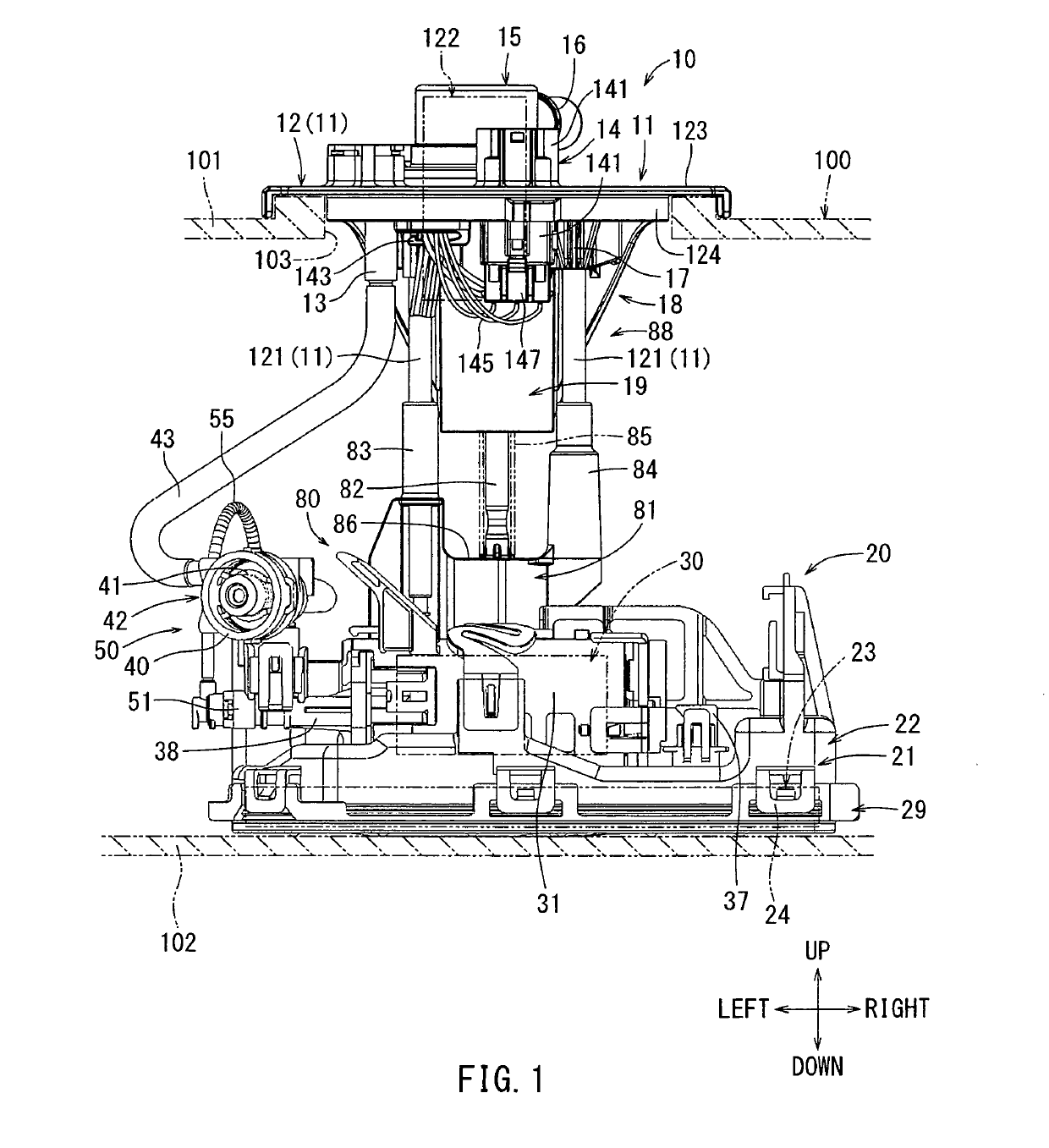
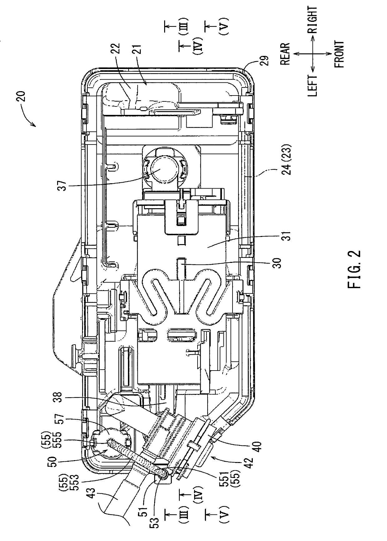
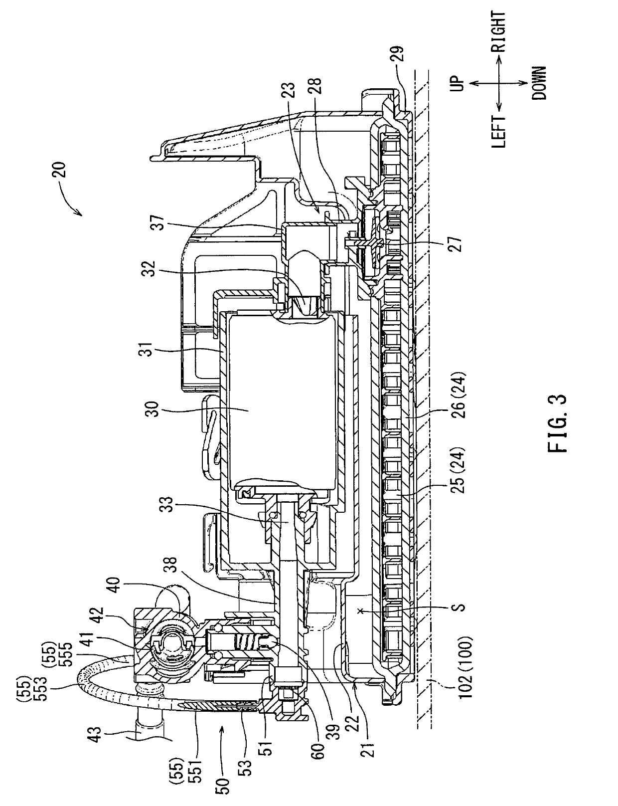
[0033]Hereinafter, embodiments for carrying out the present disclosure will be described with reference to the drawings. Incidentally, FIG. 1 is a front view showing the fuel supply device 10. FIG. 2 is a top view showing the pump unit 20. FIG. 3 is a cross-sectional view taken along (III)-(III) in FIG. 2. FIG. 4 is a cross-sectional view taken along (IV)-(IV) in FIG. 2. FIG. 5 is a cross-sectional view taken along (V)-(V) in FIG. 2. Each of the frontward, rearward, upward, downward, leftward and rightward directions as shown in the drawings corresponds to each of the corresponding directions of a vehicle. Specifically, the frontward / rearward direction corresponds to the longitudinal vehicle length direction, the rightward / leftward direction corresponds to the vehicle width direction and the upward / downward direction corresponds to the vehicle height direction. The fuel supply device 10 is installed into the fuel tank 100 mounted on an automobile as a vehicle. The fuel supply device...


PUM


Abstract

When a fuel tank is inclined at a negative slope and tilted to the right side, it may be tilted such that a position of a mesh member is relatively higher than a position of a vapor outlet of a vapor outlet passage. In this case, air may enter into a leak passage from an outlet port such that interfacial tension is generated in the mesh member. The interface between fuel and air is present at the mesh member, and the interfacial tension generated at the interface serves to prevent air from entering into a discharge pipe.

Description

CROSS-REFERENCE TO RELATED APPLICATIONS[0001]The present application is a U.S. National Phase entry of, and claims priority to, PCT Application No. PCT / JP2017 / 002076, filed Jan. 23, 2017, which claims priority to Japanese Patent Application No. 2016-029969, filed Feb. 19, 2016, both of which are hereby incorporated herein by reference in their entireties for all purposes.STATEMENT REGARDING FEDERALLY SPONSORED RESEARCH OR DEVELOPMENT[0002]Not applicable.BACKGROUND[0003]The present disclosure relates to a fuel supply device that is installed into a fuel tank and serves to supply fuel from within the fuel tank to an internal combustion engine.[0004]Conventionally, a fuel tank for storing fuel such as gasoline is mounted on an automobile (vehicle). A fuel supply device configured to supply fuel from the tank to an engine (internal combustion engine) as disclosed in Japanese Laid-Open Patent Publication No. 2009-144542 is installed inside the fuel tank. The fuel supply device generally ...

Claims


Application Information

Patent Timeline
Patent Type & Authority Applications(United States)
IPC IPC(8): F02M37/20F02M37/00F02M37/10F02M37/44F02M37/50
CPCF02M37/0017F02M37/20F02M37/103F02M37/04F02M37/10F02M37/50F02M37/44F02M37/22
Inventor HIGASHI, SHINYAYOSHIDA, KOJINIWA, KENSUKEKARIY A, HIROYASUTAKEMURA, MORIHIROFUKUI, TATSUKIIIDA, AKIRAFUJIWARA, TAKUHITOMORIZONO, TAKEAKIYAMAUCHI, TAKEHIRO
Owner AISAN IND CO LTD
Why Eureka
Try Eureka