
Butterfly valve seat ring and butterfly valve provided with same

a butterfly valve and seat ring technology, which is applied in the direction of valve details, valve arrangements, valve housings, etc., can solve the problems of increased operation torque or impediment to the rotation of the valve element to a valve closing position, and reduce sealability, so as to facilitate the mounting of the seat ring and facilitate the assembly of the butterfly valve. , the effect of reducing the sealing for

Active Publication Date: 2019-10-31
ASAHI YUKIZAI KOGYO CO LTD
View PDF3 Cites 1 Cited by
  • Summary
  • Abstract
  • Description
  • Claims
  • Application Information

AI Technical Summary

Benefits of technology

The invention provides a butterfly valve with an arcuate projection on the seat ring to prevent movement in the flow passage axis direction and improve sealability. The arcuate projection is formed separately from the through-holes on the seat ring, allowing for easy mounting on the valve body and facilitating assembly of the butterfly valve.

Problems solved by technology

When the sealability decreases and a fluid enters between the outer peripheral surface of the seat ring and the inner peripheral surface of the internal flow passage of the valve body through a gap between the valve stem and the inner peripheral surface of the through-hole of the seat ring, the seat ring is swelled inward, which may cause an increase in operation torque or an impediment to the rotation of the valve element to a valve closing position.
Further, the butterfly valve may pose a problem that the seat ring is moved in the flow direction by friction caused between the outer peripheral edge surface of the valve element and the inner peripheral surface of the seat ring during the rotation of the valve element accompanied by the opening and closing of the valve or an action of fluid pressure on the seat ring in closing the valve, so that the sealability decreases.

Method used


Image

  • Butterfly valve seat ring and butterfly valve provided with same
  • Butterfly valve seat ring and butterfly valve provided with same
  • Butterfly valve seat ring and butterfly valve provided with same

Examples


Embodiment Construction

[0024]While an embodiment of a butterfly valve seat ring and a butterfly valve using the same according to the present invention will be described below with reference to the drawings, it goes without saying that the present invention should not be limited to the embodiment.

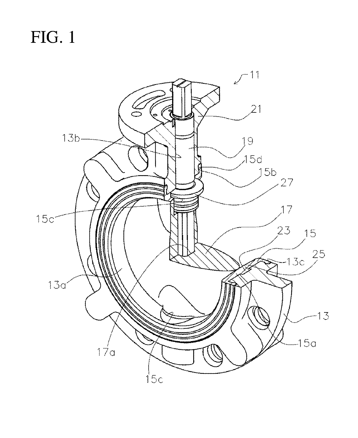
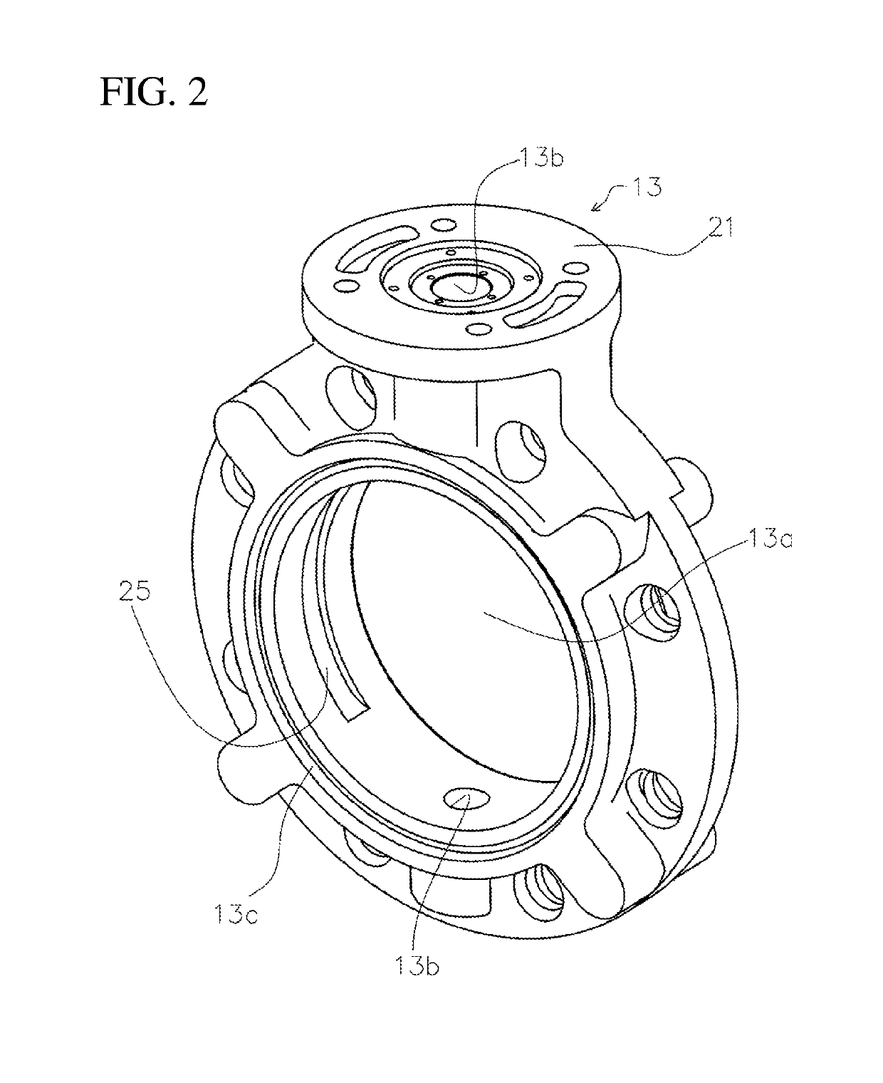
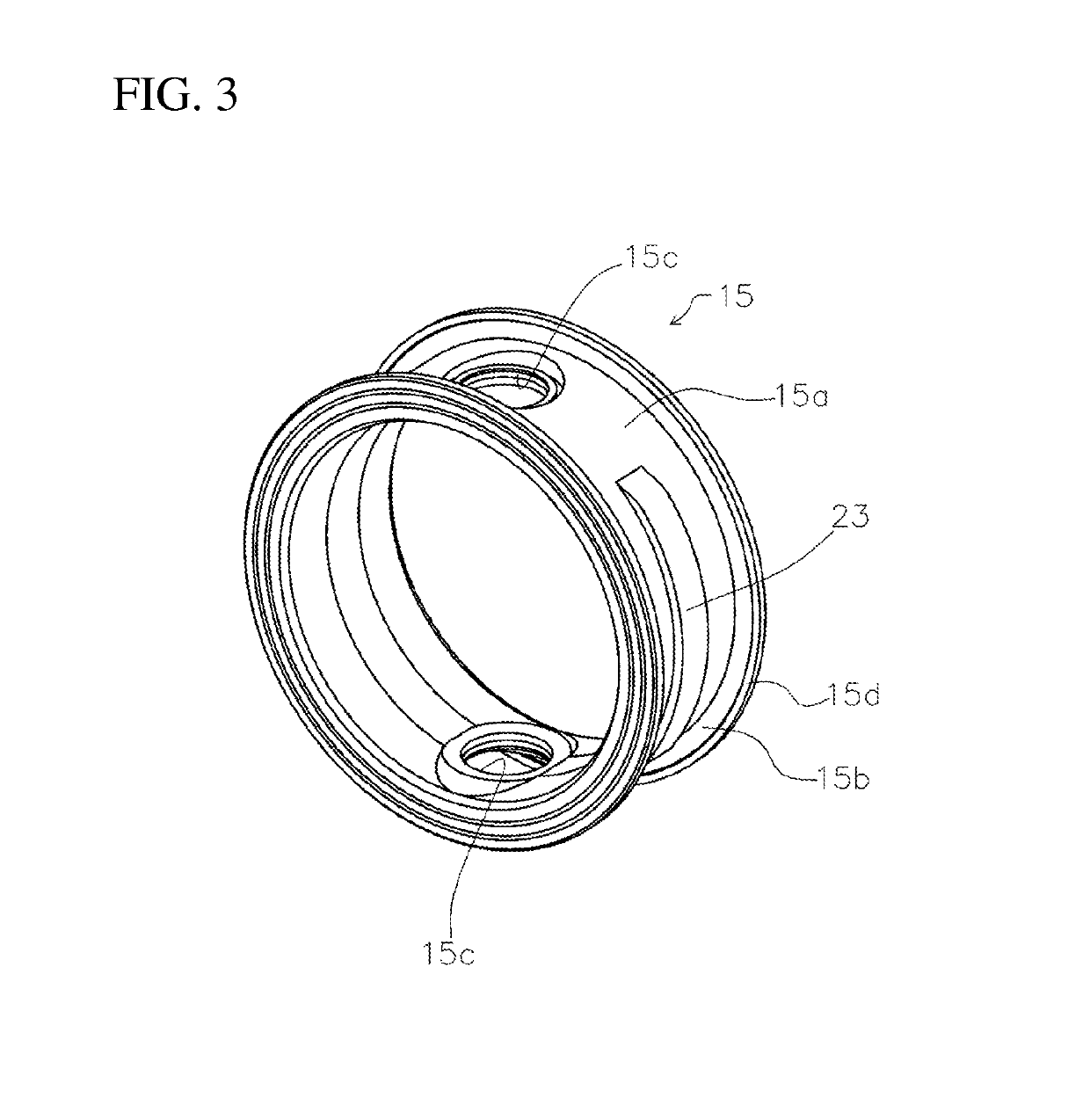
[0025]First, an overall configuration of a butterfly valve 11 will be described with reference to FIG. 1 to FIG. 3. The butterfly valve 11 includes a valve body 13, a seat ring 15, a valve element 17, and a valve stem 19.

[0026]The valve body 13 is formed of metal material, synthetic resin material such as polypropylene (PP), or any other rigid material and has a substantially cylindrical shape in which an internal flow passage 13a extending along the flow passage axis is formed. Further, a top flange 21 of a substantially disk shape is provided at an upper portion of the valve body 13. The valve body 13 is formed with valve stem support holes 13b, 13b extending from the internal flow passage 13a and facing each o...


PUM


Abstract

A seat ring for a butterfly valve is mounted on an inner peripheral surface of an internal flow passage extending along the flow passage axis in a valve body of the butterfly valve, so that an outer peripheral edge surface of a valve element supported to be rotatable in the internal flow passage by a valve stem supported by the valve body abuts on the seat ring. The seat ring includes a ring body having a cylindrical shape and extending in the center axis direction, and the ring body is formed at positions opposite to each other in a radial direction of the ring body with a pair of through-holes for allowing the valve stem to pass through. On an outer peripheral surface of the ring body, arcuate projections extending in a circumferential direction are formed apart from the pair of through-holes.

Description

TECHNICAL FIELD[0001]The present invention relates to a butterfly valve seat ring and a butterfly valve using the same which are suitably used for piping lines of various industries, such as chemical factories, water and sewage, agriculture and fishery, a semiconductor manufacture field, and a food field.BACKGROUND ART[0002]A butterfly valve includes a valve body having an internal flow passage formed therein, a seat ring mounted on the inner peripheral surface of the internal flow passage of the valve body, a valve stem extending through the seat ring and supported by the valve body, and a valve element disposed in the seat ring mounted on the inner peripheral surface of the internal flow passage of the valve body and fixedly mounted to the valve stem so as to rotate with the valve stem. The valve element is rotated using the valve stem in the valve body so that the outer peripheral edge surface of the valve element is brought into pressure contact with or separated from the inner ...

Claims


Application Information

Patent Timeline
Patent Type & Authority Applications(United States)
IPC IPC(8): F16K1/226
CPCF16K1/2263F16K1/2265F16K1/224F16K1/42F16K27/0218
Inventor YAMAMOTO, YUKIHISAYAMASHITA, SEIJI
Owner ASAHI YUKIZAI KOGYO CO LTD
Learn More