

Method for leakage detection of underground pipeline corridor based on dynamic infrared thermal image processing
a dynamic infrared thermal image and pipeline technology, applied in fluid tightness measurement, instruments, roads, etc., can solve the problems of unreliable detection methods, affecting the identification of crack areas, and obtaining normal images only the gray space information of underground pipeline corridors, so as to reduce image resolution and contrast, the effect of less information
Active Publication Date: 2019-10-31
DU YUCHUAN
View PDF0 Cites 60 Cited by
- Summary
- Abstract
- Description
- Claims
- Application Information
AI Technical Summary
Benefits of technology
[0073]Compared with the background, the crack target that needs to be identified in the images has less information. Besides, in the process of image acquisition and transmission, the resolution and contrast of the image are reduced due to interference of many factors. Therefore, after filtering and denoising the image, the graphics are further enhanced, so that the crack target that we are interested in is more prominent, providing a basis for the subsequent segmentation recognition algorithm.
[0074]Image threshold segmentation is a widely-used segmentation technique. Based on the difference between the target region and the background in the image, the image is treated as two types of regions (target region and background region) with different gray levels. The combination of a reasonable threshold is selected to determine whether each pixel in the image should belong to the targe
Problems solved by technology
Normal images can only obtain the gray space information of the underground pipeline corridor environment space, pipeline lines and leakage cracks.
The reason why normal images are difficult to identify the leakage cracks is that the surface material of the pipe is grainy, and the gradation of gray scale often affects the identification of the crack area.
However, the detection method of obtaining the crack width by the identification of the crack pixel width to determine the crack severity is unreliable, because the crack width of a few millimeters may have only a few pixels in the image, and is subjected to image processing such as noise reduction.
So, it is difficult to discriminate the crack only by the gray scale information of the crack acquired by the ordinary image.
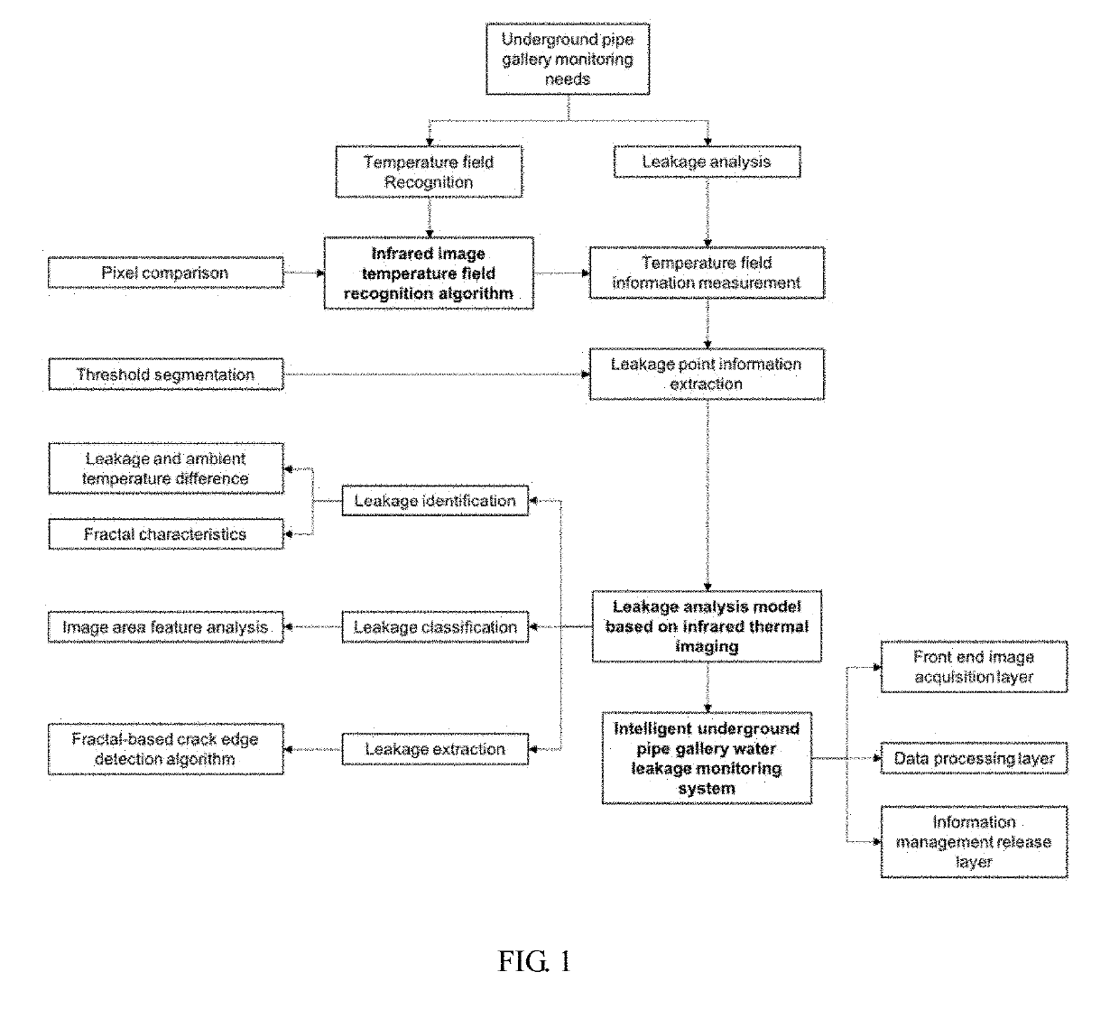
(1) The underground pipeline corridor space is dark and damp. Using traditional methods to detect the leakage of internal pipes will be subject to various restrictions due to dim light, low temperature, and other factors, resulting in large errors. Therefore, the present invention clearly recognizes the obvious difference between the leakage area and the pipeline corridor environment through the infrared thermal image, can effectively identify the leakage point, and can display parameters such as the size of the leakage damage by using image processing technology.
(2) Leakage in underground integrated pipeline corridor is mainly divided into the leakages caused by small cracks, the leakages caused by local area damage and the leakages caused by loose pipe joint. In the above three cases, the features of the leak point are different, so the image taken by the infrared camera will show different characteristics. Therefore, the present invention needs to set a scientific infrared data information screening standard to distinguish different kinds of leakage conditions, thereby ensuring the applicability of the detection results, and providing a possibility for the targeted maintenance according to the specific classification.
(3) After successfully identifying the leakage damage in the underground integrated pipeline corridor, it is necessary to promptly extract the position information of the leakage point and feed it back to the maintenance department to facilitate the immediate repair of the dangerous leakage point in the pipeline corridor. The present invention provides an accurate and efficient positioning technology, and realizes the positioning of the leakage point by screening and matching the interest domain graphic and the template graphic.
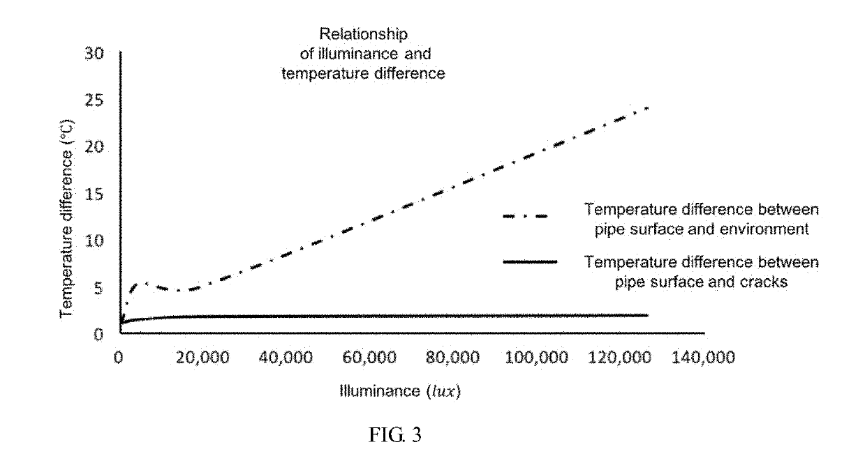
Therefore, the more serious the crack development, under the same conditions, the difference between the performance and the surface temperature of the pipe will be greater.
The greater the damage caused to the pipeline, the greater the possibility of further water damage.
At the same time, the corrosion of the material around the crack is also one of the factors affecting the severity of the crack.
The naked eye can estimate the corrosion of the material around the crack, but how to accurately and simply reflect the development degree of the crack is an urgent problem to be solved in the project.
(1) When the results of the two are the same, the test is considered correct;
(2) When the results of the two are different, if the result of the fiber optic sensor indicates that leakage has occurred, and the infrared temperature sensing system shows that no leakage has occurred, it is considered that leakage has occurred; if not, it is considered that no leakage has occurred;
(3) When one instrument does not have feedback data, the result of another data is taken;
(4) When there is no feedback data, the system is considered to be faulty and needs to be timely repaired.
The
Method used
View moreImage
Smart ImageViewing Examples

Examples
 PUM
| Property | Measurement | Unit |
|---|---|---|
| Length | aaaaa | aaaaa |
| Electrical conductance | aaaaa | aaaaa |
| Temperature | aaaaa | aaaaa |
Abstract
A method for leakage detection of underground pipeline corridor based on dynamic infrared thermal image processing. The leakage can be detected by the following steps, including: converting infrared thermal videos into infrared thermal images; obtaining the gray scale information and temperature information of internal environment of the underground pipeline corridor. The gray scale information can realize the conventional target of pipe line state identification inside the pipeline corridor, and the temperature information can be used to detect the pipe leakage.
Description
CROSS-REFERENCE TO RELATED APPLICATIONS[0001]This application is a continuation of International Application No. PCT / IB2017 / 058540 with a filing date of Dec. 30, 2017, designating the United States, now pending, which claims the benefit of priority from International Application No. PCT / IB2016 / 058109 with a filling date of Dec. 30, 2016. The content of the aforementioned applications, including any intervening amendments thereto, is incorporated herein by reference.TECHNICAL FIELD[0002]The present invention relates to image processing and leakage detection, and more particularly to a method for leakage detection of an underground pipeline corridor based on dynamic infrared thermal image processing. By introducing infrared thermal image, the gray scale information and temperature information of the internal environment of the underground pipe pipeline corridor can be obtained. The gray scale information can realize the conventional target of pipeline line state identification inside ...
Claims
Login to View More Application Information
Patent Timeline
 IPC IPC(8): F17D5/02G01M3/00
CPCG01M3/002F17D5/02G01M3/38G01N3/08G01N25/72F17D5/06G01N21/88G01N21/95E01C7/18E01C23/01G01M3/00G01M5/0033G01M5/0066G01N33/42G01N2021/8845
InventorDU, YUCHUANSUN, LIJUNPAN, NINGJIANG, SHENGCHUANLIU, CHENGLONGYAN, JUNWANG, QIN
OwnerDU YUCHUAN