Modular distributed system for the acoustic detection of underwater threats in a sensitive zone

a distributed system and acoustic detection technology, applied in the field of acoustic detection systems, can solve the problems of limiting the processing gain of such sonars, affecting the detection accuracy of underwater instruments, and exposing certain infrastructures that are accessible underwater to various types of threats

Pending Publication Date: 2019-10-31
THALES SA
View PDF21 Cites 5 Cited by
  • Summary
  • Abstract
  • Description
  • Claims
  • Application Information

AI Technical Summary

Benefits of technology

[0023]In particular, the position of each receiver RX may be such that the surface area ire(i) of a triangle i is less than or equal to Rmono2·cos(θMi) and greater than or equal to Rmono2 cos(θi) / 2, the triangle i being formed by a point coinciding with the transmitter of the group and two points coinciding with two adjacent receivers of the layer, the angle θi denoting the angle of insonification of the receiver RXi with respect to the axis of symmetry and the angle θMi denoting the angle between the axis of symmetry, on the one hand, and the axis passing through the transmitter and through the point Mi corresponding to the middle of the segment defined by the receiver RX1 and the previous adjacent receiver RXi−1, on the other hand.
[0024]In one embodiment, the receivers of each group may be arranged in at least one layer, whereas, for at least one group of the system, the receivers of at least one layer of the group describe a curved form, the position of each receiver RXi being such that the surface area ire(i) of a triangle i is less than or equal to Rmono2·cos(θMi) and greater than or equal to Rmono2 cos(θi) / 2, the triangle i being formed by a point coinciding with the transmitter of the group and two points coinciding with two adjacent receivers RXi and RXi−1 of the layer, the angle θi denoting the angle of insonification of the receiver RXi with respect to the axis passing through the transmitter and perpendicular to the straight line passing through the receivers RXi and RXi−1, the angle θMi denoting the angle between the axis, on the one hand, and the axis passing through the transmitter and through the point Mi corresponding to the middle of the segment defined by the receiver RX1 and the previous adjacent receiver RXi−1, on the other hand.

Problems solved by technology

Certain infrastructures that are accessible underwater may be exposed to various types of threat, such as underwater threats with or without divers, which are potentially propelled with a range capability and at a high speed.
Such threats may for example deposit an explosive charge on the infrastructure.
For conventional DDS monostatic sonars, which are used to detect divers over several hundred meters, the duration of the pulse is generally less than 100 msec (milliseconds), thereby limiting the processing gain of such sonars.
Moreover, such sonars are subject to absorption losses due to high operating frequencies.
In practice, it is extremely difficult to use a plurality of “chained” anti-diver monostatic sonars because, if it is necessary to provide sonars that are close enough to one another in order to detect, each transmitter disrupts the neighbouring receiver situated at a close distance, which would by contrast require the transmitters to be spaced.
Current detection systems do not make it possible to detect, with sufficient prior warning, a fast target (a “fast” target with traction assistance conventionally has a speed of approximately 2 to 3 knots, whereas a “slow” target without traction assistance conventionally has a speed of approximately 1 knot), at distances that are far enough away from the infrastructure to allow preventive actions (alarms, target interception, etc.) to be implemented before the threat reaches the infrastructure.
For example, due to absorption at high frequency, it is not currently possible to detect threatening divers three times further away who are traveling three times faster (3 knots versus 1 knot) and who are equipped with a small traction device, who have both low noise in passive mode and a low target index in active mode.

Method used


Image

  • Modular distributed system for the acoustic detection of underwater threats in a sensitive zone
  • Modular distributed system for the acoustic detection of underwater threats in a sensitive zone
  • Modular distributed system for the acoustic detection of underwater threats in a sensitive zone

Examples


Embodiment Construction

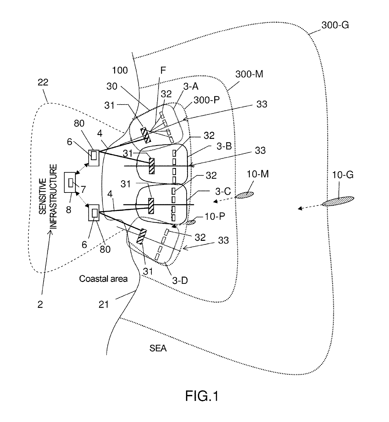
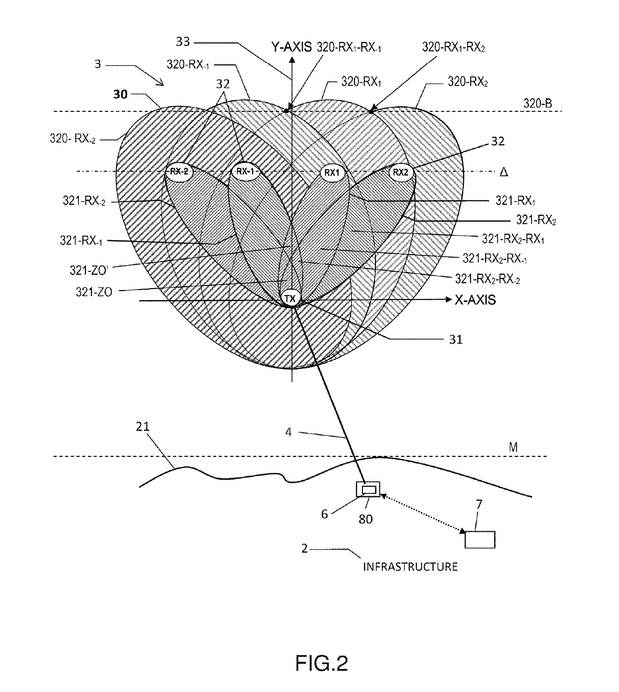
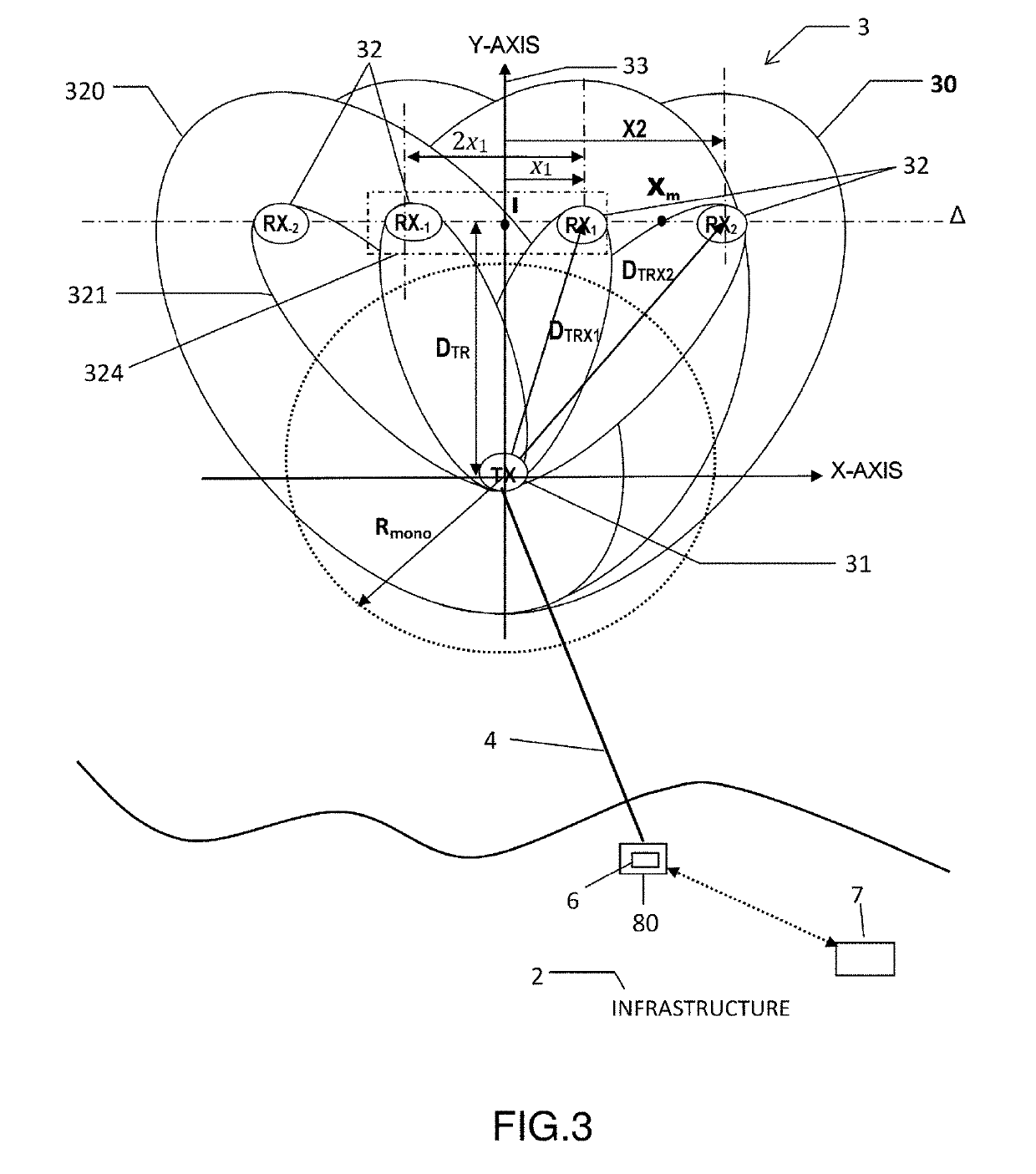
[0070]According to some embodiments according to the invention, what is proposed is an acoustic detection system (also called a “surveillance system” below) configured so as to detect at least partly submerged targets in a sensitive area defined with respect to an infrastructure, the detection system comprising at least one multistatic detection group, each multistatic detection group defining a detection area, and comprising:[0071]a submerged transmitter;[0072]a plurality of submerged receivers comprising at least two receivers (RX), each receiver of a given group forming, with the transmitter (TX) of the group, a bistatic pair {TX, RX}.

[0073]Each bistatic pair {TX, RX} generates an elementary detection area (320) surrounding a blind zone, the detection area of the group being formed by all of the elementary detection areas of the receivers of the group.

[0074]In some embodiments, the blind zone (also called “blind area” or “area of non-detection”) of each receiver in a given detect...


PUM


Abstract

An acoustic detection system for detecting at least partly submerged targets in a sensitive area defined with respect to an infrastructure, wherein the system includes at least one multistatic detection group, each multistatic detection group defining a detection area, and comprising: a submerged transmitter transmitting at low frequencies; a plurality of submerged receivers comprising at least two receivers, each receiver of a given group forming, with the transmitter of the group, a bistatic pair, each bistatic pair generating an elementary detection area surrounding a blind zone, the detection area of the group being formed by all of the elementary detection areas of the receivers of the group, the blind zone of each receiver in a given detection group being at least partly covered by the elementary detection areas of the neighbouring receivers of the detection system.

Description

FIELD OF THE INVENTION[0001]The invention relates generally to acoustic detection systems, and in particular to an acoustic detection system for detecting various threatening targets, penetrating into a sensitive area defined with respect to an infrastructure to be protected.PRIOR ART[0002]Certain infrastructures that are accessible underwater may be exposed to various types of threat, such as underwater threats with or without divers, which are potentially propelled with a range capability and at a high speed. Such threats may for example deposit an explosive charge on the infrastructure. Examples of sensitive infrastructures comprise:[0003]infrastructures opening out onto a wide entrance of a military or civilian port, of a refinery or any other high-value coastal installation able to be threatened by a seaborne threat;[0004]offshore oil platforms;[0005]surface ship that remain stationary or mobile in an area, and having a low-frequency acoustic transmission capability.[0006]Speci...

Claims


Application Information

Patent Timeline
Patent Type & Authority Applications(United States)
IPC IPC(8): G01S15/00G01S15/04G01S7/539
CPCG01S15/003G01S15/04G01S7/539G01S15/88G01S15/42
Inventor RAILLON, LOUIS
Owner THALES SA
Why Eureka
Try Eureka