Coil component

a coil and component technology, applied in the field of coil components, can solve problems such as loss of characteristic balance between the lines, and achieve the effects of enhancing inductance, reducing the difference between the line length of the lower and the upper coil, and reducing the difference between the line lengths of the lower and upper coils

Active Publication Date: 2019-10-31
TDK CORPARATION
View PDF0 Cites 0 Cited by
  • Summary
  • Abstract
  • Description
  • Claims
  • Application Information

AI Technical Summary

Benefits of technology

[0006]According to the present invention, the coil diameter of the lower coil is larger than the coil diameter of the upper coil, whereby the line length per turn is larger in the lower coil than in the upper coil. This reduces a difference between the line lengths of the lower and upper coils and ideally makes the line lengths of the lower and upper coils coincide with each other, thus making it possible to reduce a difference in DC resistance between the lower and upper coils.
[0007]In the present invention, the first and second areas may be arranged in a first direction perpendicular to the coil axis, the third and fourth areas may be arranged in the first direction, the first and third areas may be arranged in a second direction perpendicular to the coil axis and first direction, and the second and fourth areas may be arranged in the second direction. A winding direction from one end of the lower coil to the other end thereof as viewed in the coil axis direction and a winding direction from one end of the upper coil to the other end thereof as viewed in the coil axis direction may be the same as each other. The number of turns of the lower coil may be larger by less than one turn than the number of turns of the upper coil. With this configuration, the coil component can be suitably used as a common mode filter. Further, since the number of turns of the lower coil is larger by less than one turn than the number of turns of the upper coil, a difference between the line lengths of the lower and upper coils can be further reduced.
[0008]The coil component according to the present invention may further include a second core disposed through the inner diameter areas of the lower and upper coils, and the diameter of the second core may be larger at a part thereof positioned in the inner diameter part of the upper coil than at a part thereof positioned in the inner diameter part of the lower coil. This enhances the inductance in the upper coil having a smaller number of turns, making it possible to reduce a difference in inductance between the lower and upper coils.
[0009]In the present invention, the lower coil may have a detour pattern having a folding structure. This can further reduce the difference between the line lengths of the lower and upper coils.
[0010]As described above, according to the present invention, in the coil component having a structure in which the lower and upper coils are stacked one on the other and disposed on the core having the mounting surface, a difference in DC resistance between the lower and upper coils can be reduced.

Problems solved by technology

As a result, the DC resistance of the upper coil is higher than that of the lower coil, which may result in loss of characteristic balance between the lines.

Method used


Image

  • Coil component
  • Coil component
  • Coil component

Examples


Embodiment Construction

[0017]Preferred embodiments of the present invention will be explained below in detail with reference to the accompanying drawings.

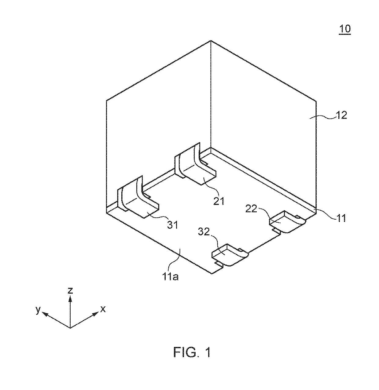
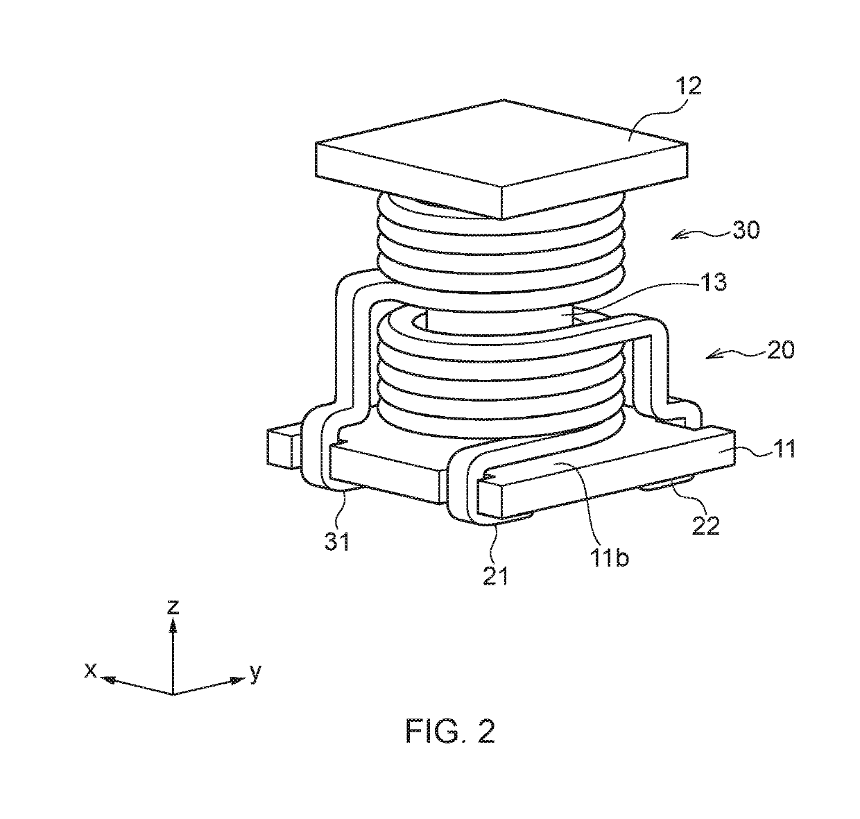
[0018]FIG. 1 is a schematic perspective view illustrating the outer structure of a coil component 10 according to a preferred embodiment of the present invention. FIG. 2 is a view for explaining the inner structure of the coil component 10 according to the present embodiment.

[0019]As illustrated in FIGS. 1 and 2, the coil component 10 according to the present embodiment includes a plate-like core 11 having a mounting surface 11a, a lower coil 20 and an upper coil 30 which are disposed on a coil placing surface 11b of the core 11, a box-like core 12 covering the lower and upper coils 20 and 30, and a rod-like core 13 disposed through the inner diameter parts of the respective lower and upper coils 20 and 30. In FIG. 2, all the side surfaces (xz- and yz-planes) of the box-like core 12 are omitted so as to make the lower and upper coils 20 and 30 visible. A...


PUM

PropertyMeasurementUnit
areaaaaaaaaaaa
diameteraaaaaaaaaa
inner diameteraaaaaaaaaa

Abstract

Disclosed herein is a coil component that includes: a first core having a mounting surface and a coil placing surface positioned opposite to the mounting surface; a lower coil placed on the coil placing surface such that a coil axis of the lower coil extends substantially perpendicular to the coil placing surface, the lower coil having one end drawn to a first area of the mounting surface and other end drawn to a second area of the mounting surface; and an upper coil substantially coaxially stacked on the lower coil, the upper coil having one end drawn to a third area of the mounting surface and other end drawn to a fourth area of the mounting surface. The lower coil is greater in a coil diameter than the upper coil.

Description

BACKGROUND OF THE INVENTIONField of the Invention[0001]The present invention relates to a coil component and, more particularly, to a coil component having a structure in which a lower coil and an upper coil are stacked one on the other and disposed on a core having a mounting surface.Description of Related Art[0002]While a common mode filter is used generally for removing common mode noise superimposed on a differential signal line, it is sometimes inserted into a power supply line. In a common mode filter for power supply, a large amount of current flows in a coil, so that a coil formed by winding a wire having a large sectional area, such as a flat-type wire is used in the power supply common mode filter. For example, International Publication WO 2015 / 005129 discloses a power supply common mode filter having a structure in which two coils each obtained by winding a flat-type wire are stacked one on the other and disposed on a core.[0003]However, the coil component described in In...

Claims


Application Information

Patent Timeline
Patent Type & Authority Applications(United States)
IPC IPC(8): H01F27/28H01F17/04H01F27/29
CPCH01F27/2828H01F2017/0093H01F2017/046H01F17/045H01F27/2804H01F27/292H01F27/306H01F3/10
Inventor SOMEYA, SHUHEIMIKOGAMI, TASUKUANZAI, YUICHITAKAHASHI, HIDEOMI
Owner TDK CORPARATION
Why Eureka
Try Eureka