Battery

a battery and battery technology, applied in the field of batteries, can solve the problems of affecting the performance and even service life of the battery cells and thus of the battery, the design of the battery of this kind is comparatively complex, and the maintenance requirements are relatively complex, so as to achieve the effect of improving the stability of the battery and high power density

Active Publication Date: 2019-10-31
MIBA BATTERY SYST GMBH
View PDF5 Cites 13 Cited by
  • Summary
  • Abstract
  • Description
  • Claims
  • Application Information

AI Technical Summary

Benefits of technology

[0007]Against this background, the object of the invention is to improve the stability of a battery having a plurality of battery modules of the type mentioned at the outset, and specifically in a structurally simple manner. In addition, the battery should have a high power density.

Problems solved by technology

By cooling the battery cells at the bottom in this manner, the temperature of the battery cells can be controlled; however, cooling of this kind is relatively sluggish due to the insulating housing of the battery cells.
Therefore, temperature peaks in the battery cells, caused for example by a high electrical power request, are compensated for relatively sluggishly, which can have an adverse effect on the performance and even the service life of the battery cells and thus of the battery.
By means of the thermal contact between the metal poles and the cooling plate, increased heat dissipation can be ensured; however, the design of a battery of this kind is comparatively complex and also requires relatively complex maintenance due to the mechanical connections.

Method used


Image

  • Battery
  • Battery
  • Battery

Examples


Embodiment Construction

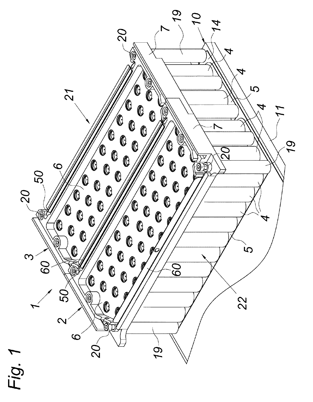
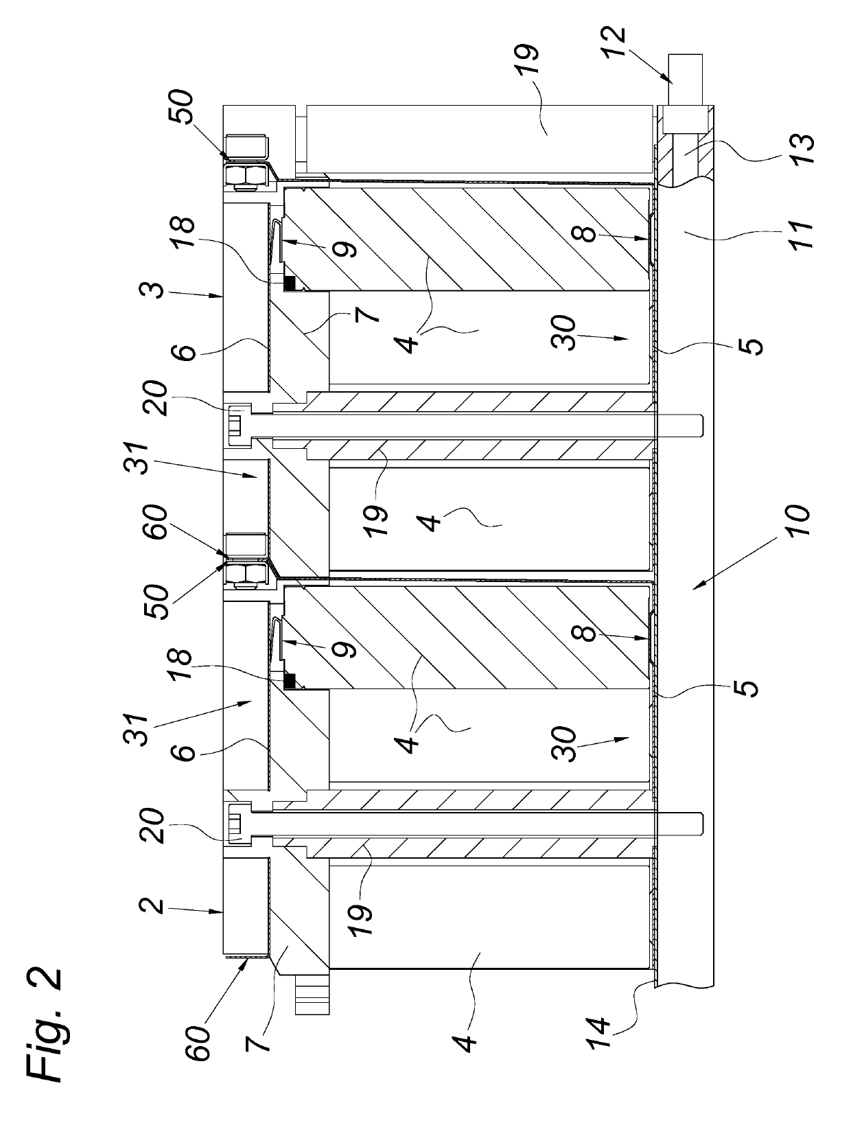
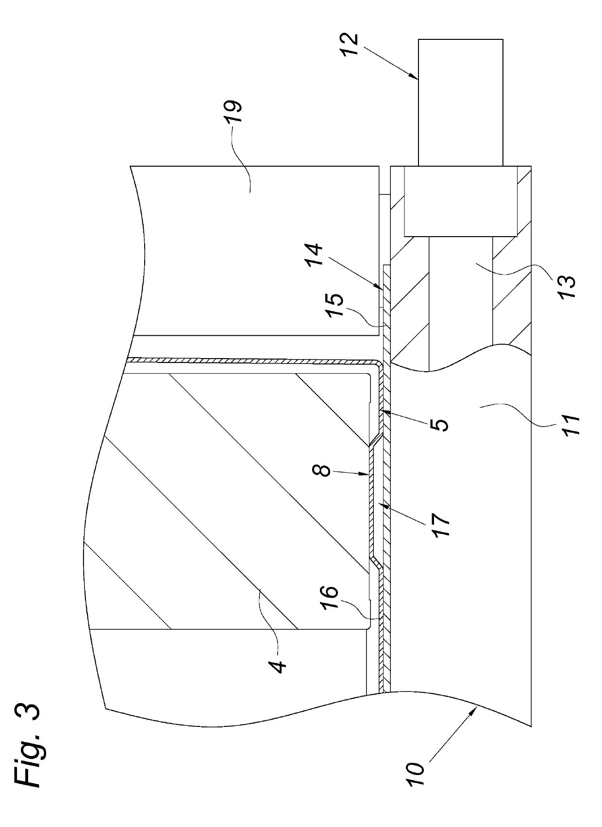
[0027]FIG. 1 shows a battery 1, by way of example, comprising a plurality of battery modules 2, 3, which battery modules 2, 3 are electrically coupled. The battery modules 2, 3 each comprise mechanical and electrical connections consisting of combined battery cells 4, metal busbars 5, 6 and a cell holder 7, which is preferably made of plastics material. The battery cells 4 protrude into holes (not shown in more detail) in the cell holder 7, as a result of which said cell holder 7 receives the battery cells 4 in a form fit and thus secures or supports said cells, as can be seen in FIG. 1; this ensures high mechanical stability in the battery modules 2, 3. The electrical poles 8, 9, specifically the positive pole 9 and negative pole 8, are arranged at opposite end faces 30, 31 of the battery modules 2, 3 and electrically joined, i.e. electrically connected, to the busbars 5 and 6 provided there, which busbars 5 and 6 function as cell connectors / cell connector boards for the battery ce...


PUM

PropertyMeasurementUnit
electrical insulationaaaaaaaaaa
heat conductingaaaaaaaaaa
electricalaaaaaaaaaa

Abstract

A battery is provided that includes a plurality of electrically coupled battery modules. Each battery module includes a plurality of combined battery cells having positive and negative poles arranged at opposing end faces of the battery module. Each battery module also includes a busbars electrically connecting said positive poles and a busbar connecting said negative poles. The battery includes an electrical insulation and a heat conducting plate arranged at one end face of the battery modules for cooling and/or heating the battery cells thereof. The heat conducting plate is provided at an end face of the battery modules that includes poles of the battery cells. The electrical insulation, which is formed as a thermal contact element, is located between the busbars of the battery modules and the heat conducting plate. The positive and negative poles of the battery cells are located on opposing end faces of each battery module.

Description

CROSS-REFERENCE TO RELATED APPLICATIONS[0001]This application is a national phase application of PCT Application No. PCT / EP2017 / 056043, filed Mar. 14, 2017, entitled “BATTERY”, which claims priority to EP16160091.1, dated Mar. 14, 2016, and which is incorporated by reference in its entirety.BACKGROUND[0002]1) Field of the Invention[0003]The invention relates to a battery comprising a plurality of electrically coupled battery modules, each comprising a plurality of combined battery cells having electrical poles, arranged at least at one end face of the battery module, as well as a plurality of busbars electrically connecting said poles, comprising electrical insulation and comprising a heat conducting plate arranged at the end face of the battery modules for cooling and / or heating the battery cells thereof.[0004]2) Description of Related Art[0005]To cool the battery cells of a battery, it is known (EP2564448B1) to fix the bottom, i.e. the lower end face, of the battery modules, consi...

Claims


Application Information

Patent Timeline
Patent Type & Authority Applications(United States)
IPC IPC(8): H01M2/10H01M2/12H01M2/20H01M10/613H01M10/615H01M10/643H01M10/653H01M10/6556H01M10/6567H01M50/213H01M50/503H01M50/507H01M50/521
CPCH01M2/1223H01M10/6556H01M10/615H01M10/653H01M2/202H01M2/1016H01M10/613H01M10/6567H01M10/643H01M10/6554Y02E60/10H01M50/213H01M50/342H01M50/507H01M50/503H01M50/521H01M50/317
Inventor REINGRUBER, MARTINJENNER-BRAUNSCHMIED, EDMUND
Owner MIBA BATTERY SYST GMBH
Why Eureka
Try Eureka