
No-welding type battery pack

a battery pack and no-welding technology, applied in the direction of secondary cell servicing/maintenance, cell components, cell component details, etc., can solve the problems of low safety low and combustible materials, so as to facilitate manufacturing and reduce the manufacturing cost of lithium secondary batteries , the assembly process of lithium secondary batteries is further simplified

Active Publication Date: 2011-05-10
LG ENERGY SOLUTION LTD
View PDF6 Cites 7 Cited by
  • Summary
  • Abstract
  • Description
  • Claims
  • Application Information

AI Technical Summary

Benefits of technology

[0012]Specifically, it is an object of the present invention to provide a battery pack wherein the assembly process of the battery pack is simplified, which enables the automatic manufacture of the battery pack, defectiveness and changes of internal resistance of the battery pack due to external impacts are minimized, the capacity of the battery is increased, and the stability of the battery pack is improved.
[0014]The battery pack according to the present invention uses the connecting member, which has a novel structure that can be easily manufactured, whereby the manufacturing costs of the battery pack are reduced, the assembly process of the battery pack is further simplified, and the drawbacks caused due to welding or soldering are removed.

Problems solved by technology

However, various combustible materials are contained in the lithium secondary battery.
As a result, there is a possibility of danger in that the lithium secondary battery can be heated or exploded due to overcharge, overcurrent, or any other external physical impacts.
In other words, the lithium secondary battery has low safety.
However, these welding or soldering operations must be carried out with vary high accuracy since the structure of the secondary battery is small.
As a result, the defective product rate is increased.
Furthermore, the welding or soldering operations are added to the manufacturing process of the product, which increases the manufacturing costs of the product.
Consequently, a method of assembling the PCM and the battery cell without performing a spot welding or soldering process is seriously required.

Method used


Image

  • No-welding type battery pack
  • No-welding type battery pack
  • No-welding type battery pack

Examples


Embodiment Construction

[0031]Now, a preferred embodiment of the present invention will be described in detail with reference to the accompanying drawings. It should be noted, however, that the scope of the present invention is not limited by the illustrated embodiment.

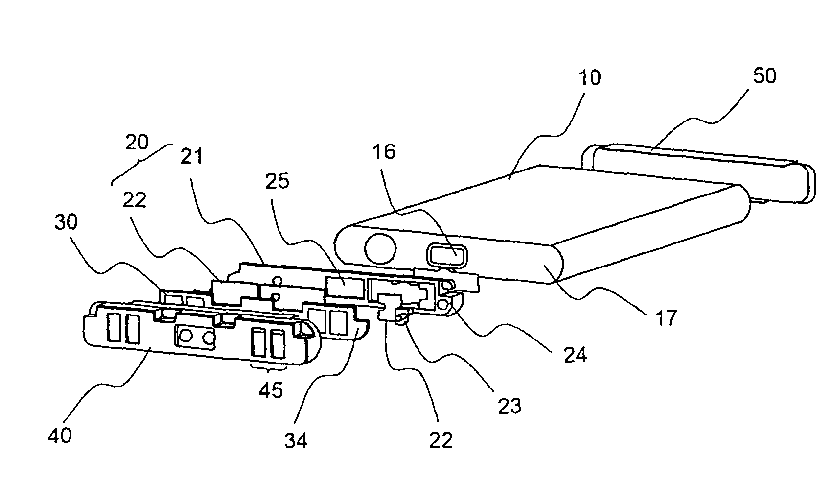
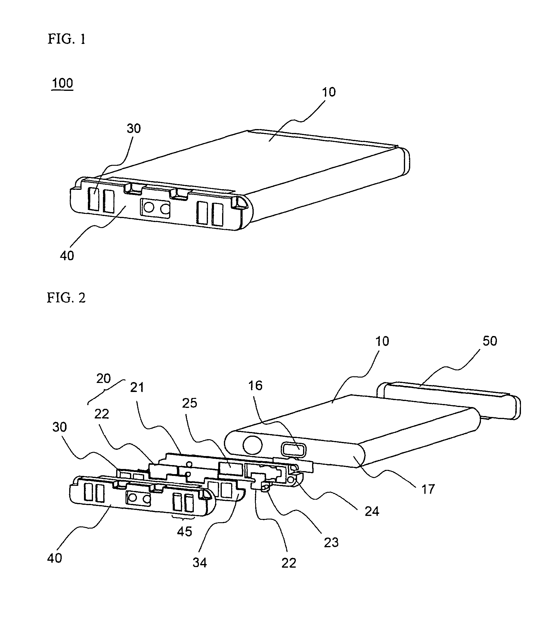
[0032]FIG. 1 is a perspective view illustrating a battery pack according to a preferred embodiment of the present invention, and FIG. 2 is an exploded perspective view of the battery pack shown in FIG. 1.

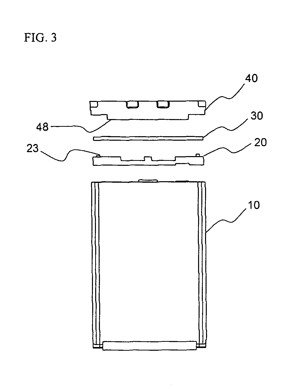
[0033]Referring to FIGS. 1 and 2, the battery pack 100 includes a connecting member (not shown) mounted to the upper end of a battery cell 10, a protection circuit module (PCM) 30 mounted to the connecting member, a cap housing 40 coupled to the battery cell 10 while the PCM 30 is mounted in the cap housing 40, and a lower cap 50 mounted to the lower end of the battery cell 10.

[0034]The connecting member 20 is mounted to an upper end surface 17 of the battery cell 10, which constitutes a cathode (or an anode) and is provided at the middle th...


PUM

PropertyMeasurementUnit
adhesionaaaaaaaaaa
energy densityaaaaaaaaaa
combustibleaaaaaaaaaa

Abstract

Disclosed herein is a battery pack, which comprises a connecting member including an insulation frame mounted to the upper end of a battery cell and a pair of connection protrusions formed at the upper end surface of the frame, the connection protrusions being in contact with electrode terminals of the battery cell, a protection circuit module (PCM) mounted to the connecting member, the PCM including connection grooves, into which the connection protrusions are inserted such that the PCM can be coupled to the connecting member, and which are connected to a protection circuit, and a cap housing coupled to the connecting member or the battery cell while the PCM is surrounded by the cap housing.

Description

FIELD OF THE INVENTION[0001]The present invention relates to a no-welding type battery pack, and, more particularly, to a battery pack, which comprises a connecting member including a pair of connection protrusions, a protection circuit module (PCM) including connection grooves, into which the connection protrusions are inserted such that the PCM can be coupled to the connecting member, and which are connected to a protection circuit, and a cap housing coupled to the connecting member or the battery cell while the PCM is surrounded by the cap housing.BACKGROUND OF THE INVENTION[0002]As mobile devices have been increasingly developed, and the demand of such mobile devices has increased, the demand of secondary batteries has also sharply increased as an energy source for the mobile devices. One of the secondary batteries is a lithium secondary battery having high energy density, high operation voltage, and excellent storage and service life characteristics, which is now widely used as...

Claims


Application Information

Patent Timeline
Patent Type & Authority Patents(United States)
IPC IPC(8): H01M14/00H01M2/00H01M2/08H01M2/02
CPCH01M10/425H01M2/1061Y02E60/10H01M50/202H01M50/271H01M50/287H01M50/20H01M50/572H01M50/147
Inventor KIM, JUNG-HWANMOON, KI EOBYOON, SEOGJINLEE, CHEOL WOONG
Owner LG ENERGY SOLUTION LTD
Learn More