
Wireless communication method for enhancing transmission efficiency through separating transmission interval in wireless local area network (WLAN) system

a wireless local area network and wireless communication technology, applied in power management, 3gpp networks, high-level techniques, etc., can solve the problems of not being able to prevent terminals from transmitting ps-, the efficiency of wireless wlans has emerged as an issue in a highly dense environment, etc., to reduce standby time, enhance power saving efficiency, and reduce collisions

Active Publication Date: 2019-10-31
ELECTRONICS & TELECOMM RES INST
View PDF24 Cites 6 Cited by
  • Summary
  • Abstract
  • Description
  • Claims
  • Application Information

AI Technical Summary

Benefits of technology

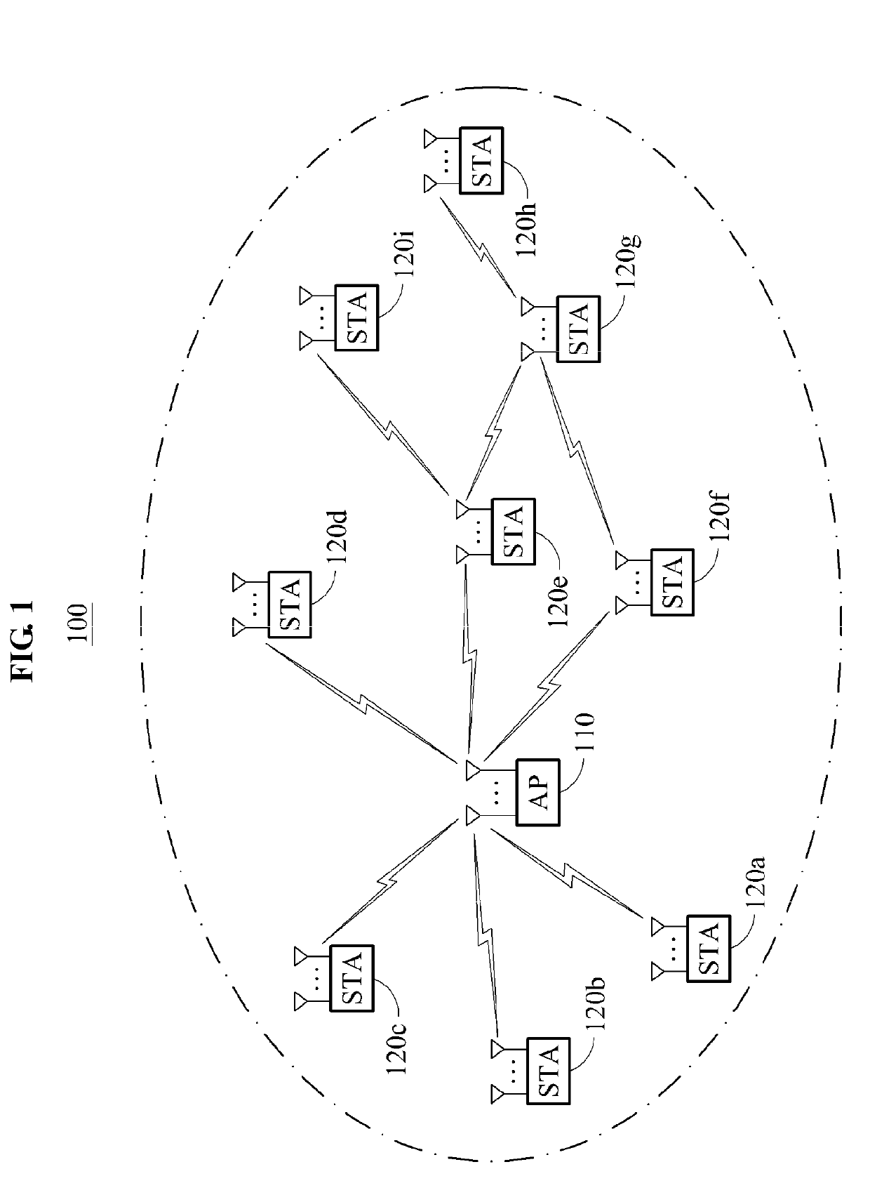
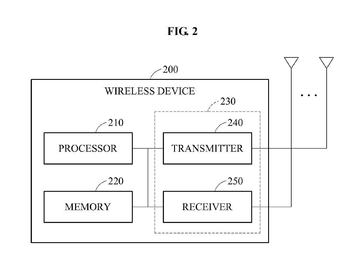
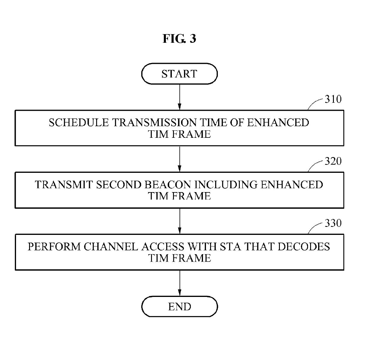
The patent text describes a method for improving wireless communication in a wireless local area network (WLAN) system by distributing the transmission interval of terminals based on their type. This helps prevent contention and degraded network performance caused by older terminals. The method also includes scheduling the transmission time of an enhanced traffic indicator map (TIM) frame and transmitting a second beacon with the enhanced TIM frame to the station at a point in time aside from the first beacon. This helps enhance the transmission efficiency and prevent contention at a specific point in time. Overall, this method improves the performance and reliability of WLAN networks.

Problems solved by technology

Currently, with a rapid increase in the use of the WLAN and the number of wireless terminals, the efficiency of the wireless WLAN has emerged as an issue in a highly dense environment.
However, in the existing frequency band, such as 2.4 GHz or 5 GHz, legacy terminals do not follow a RAW operation and thus, the RAW may be readily introduced.
However, since such beacons are generally used to enhance a network discovery rate and do not have traffic indicator map (TIM) information, it may not be possible to prevent terminals from transmitting PS-polls at a time at a transmission point in time of a beacon.

Method used


Image

  • Wireless communication method for enhancing transmission efficiency through separating transmission interval in wireless local area network (WLAN) system
  • Wireless communication method for enhancing transmission efficiency through separating transmission interval in wireless local area network (WLAN) system
  • Wireless communication method for enhancing transmission efficiency through separating transmission interval in wireless local area network (WLAN) system

Examples


Embodiment Construction

Object

[0009]Embodiments provide a method that may prevent an occurrence of contention by distributing a transmission interval of terminals so that different device types of terminals may perform transmission in different time intervals even in 2.4 GHz and 5 GHz, and may prevent a degradation in the network performance by a legacy terminal by enabling a terminal, such as 11ac terminal and 11ax terminal, to perform transmission in a time interval different from a time interval of the legacy terminal.

[0010]Embodiments also provide a method of enhancing the transmission efficiency by distributing a transmission interval based on a device type that may prevent a degradation in the overall network efficiency and may also prevent contention from occurring at a specific point in time, when a legacy terminal is mixed.

Solution

[0011]According to an aspect, there is provided a wireless communication method performed at an access point, the method including scheduling a transmission time of an e...


PUM


Abstract

Provided is a wireless communication method performed at an access point to enhance the transmission efficiency in a wireless local area network (WLAN) system, the method including scheduling a transmission time of an enhanced traffic indicator map (TIM) frame based on a type of a station, and transmitting a second beacon including the enhanced TIM frame to the station at a point in time aside from a transmission point in time of a first beacon.

Description

CROSS REFERENCE TO RELATED APPLICATIONS PARAGRAPH[0001]This application is a continuation of and claims priority to U.S. application Ser. No. 14 / 946,551 filed Nov. 19, 2015, which claims the priority benefit of Korean Patent Application Nos. 10-2014-0161655 filed on Nov. 19, 2014, and 10-2015-0162445 filed on Nov. 19, 2015, in the Korean Intellectual Property Office, the disclosures of which are incorporated herein by reference.TECHNICAL FIELD[0002]Embodiments relate to technology for performing wireless communication by distributing a transmission interval based on a type of a terminal in a wireless local area network (WLAN) system.RELATED ART[0003]In general, a local area network (LAN) that is a near field communication network is divided in a wired LAN and a wireless LAN (WLAN). The WLAN employs a method of performing communication on a network using propagation instead of using a cable. The WLAN has been introduced as an alternative for overcoming difficulties found in installat...

Claims


Application Information

Patent Timeline
IPC IPC(8): H04W52/02H04W74/04
CPCY02D70/146Y02D70/142H04W74/04Y02D70/1264Y02D70/00Y02D70/1262H04W48/12H04W84/12Y02D70/1224H04W52/0206Y02D70/166Y02D30/70H04W72/23
Inventor KIM, IL GYULEE, YU ROLEE, JAE SEUNGPARK, JAE WOOCHOI, JEE YON
Owner ELECTRONICS & TELECOMM RES INST
Learn More