Dehumidifier

Active Publication Date: 2019-11-14
NIHON KOHDEN CORP
View PDF0 Cites 0 Cited by
  • Summary
  • Abstract
  • Description
  • Claims
  • Application Information

AI Technical Summary

Benefits of technology

[0014]According to the configuration, when the dehumidifier is not activated, the membrane of the membrane dryer can be prevented from absorbing the humidity of the ambient air. In other words, the water content of the membrane can be suppressed from i

Problems solved by technology

However, such a hollow fiber membrane has a large water content capacity

Method used


Image

  • Dehumidifier
  • Dehumidifier
  • Dehumidifier

Examples


Example

[0018]An embodiment will be described in detail with reference to the accompanying drawings. In the drawings, in order to make the components to be described, to have a recognizable size, their scales are appropriately changed.

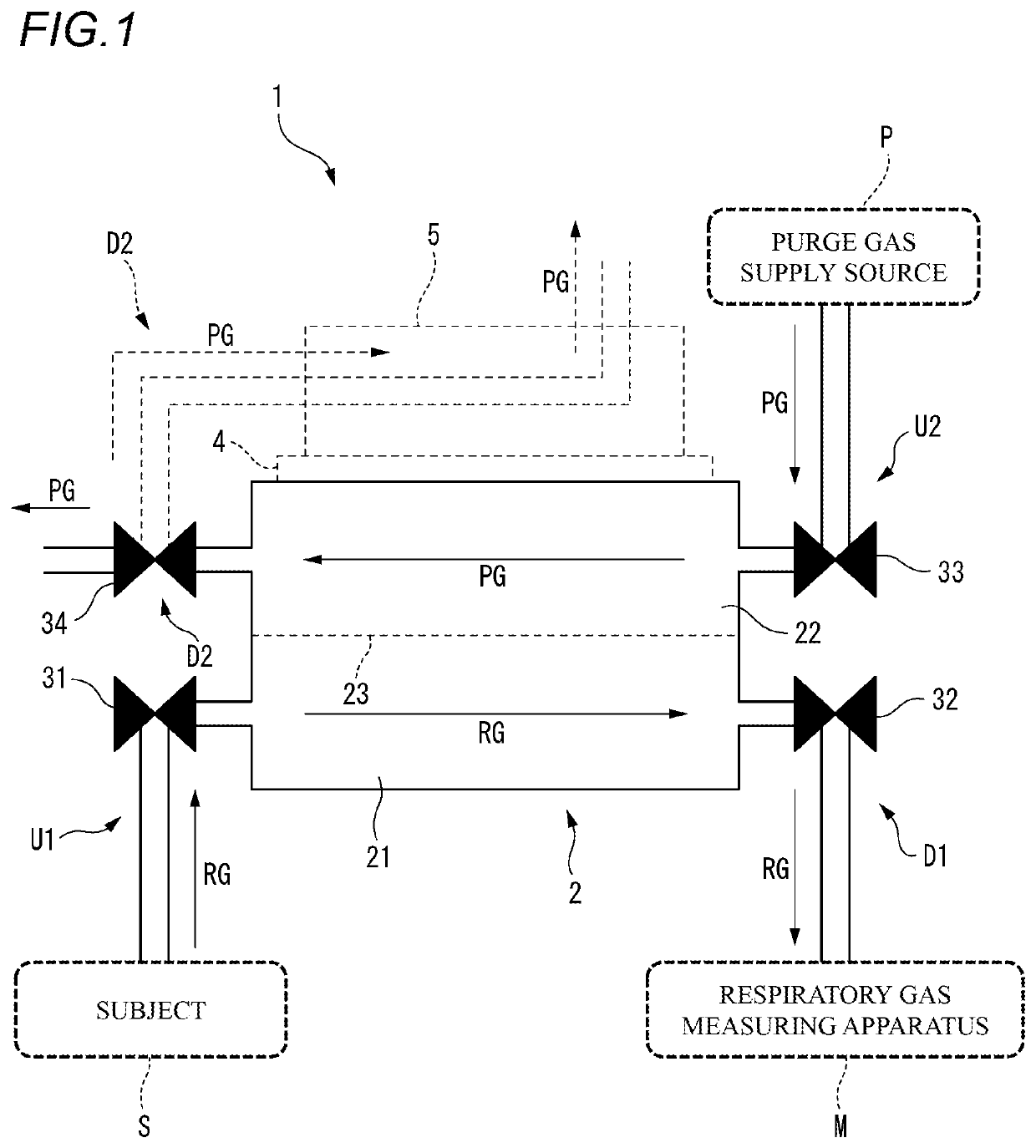
[0019]FIG. 1 diagrammatically illustrates the configuration of a dehumidifier 1 of the embodiment. The dehumidifier 1 is connected to a respiratory gas measuring apparatus M which measures the respiratory gas of a subject S.

[0020]The dehumidifier 1 may include a membrane dryer 2. The membrane dryer 2 may include a first flow path 21, a second flow path 22, and a membrane 23. The membrane 23 is formed by a hollow fiber membrane which is made of, for example, a fluorine resin. The membrane 23 separates the first flow path 21 and the second flow path 22 from each other.

[0021]The first flow path 21 is a flow path through which the respiratory gas RG of the subject S is allowed to pass. The respiratory gas RG is a gas which is to be measured by the respiratory gas ...


PUM


Abstract

A dehumidifier is connected to a respiratory gas measuring apparatus. A membrane dryer has a first flow path through which a respiratory gas of a subject passes, and a second flow path through which a purge gas passes. A first normally-closed electromagnetic valve is disposed in a first upstream flow path that communicates with the first flow path. A second normally-closed electromagnetic valve is disposed in a first downstream flow path that communicates with the first flow path. A third normally-closed electromagnetic valve is disposed in a second upstream flow path that communicates with the second flow path. A fourth normally-closed electromagnetic valve is disposed in a second downstream flow path that communicates with the second flow path.

Description

CROSS-REFERENCE TO RELATED APPLICATIONS[0001]This application is based on and claims priority under 35 USC 119 from Japanese Patent Application No. 2018-089955 filed on May 8, 2018, the contents of which are incorporated herein by reference.TECHNICAL FIELD[0002]The presently disclosed subject matter relates to a dehumidifier which is to be connected to a respiratory gas measuring apparatus for measuring a respiratory gas of a subject.BACKGROUND ART[0003]Patent Literature 1 discloses an example of a respiratory gas measuring apparatus. In a measurement of a respiratory gas, the humidity difference between the expiration and inspiration of a subject may cause a measurement error. Therefore, it is proposed that the respiratory gas is dehumidified by passing the gas through a membrane dryer having a hollow fiber membrane, thereby reducing the humidity difference between the expiration and the inspiration.CITATION LISTPatent Literature[0004]Patent Literature 1: JP-A-2012-163544SUMMARY OF...

Claims


Application Information

Patent Timeline
IPC IPC(8): B01D53/26B01D53/22B01D63/02A61B5/097
CPCB01D53/22A61B5/097B01D53/268B01D2053/224B01D63/02B01D2311/10B01D2313/18B01D2313/22F24F2003/1435B01D2259/4533
Inventor SAEKI, KOTAKURAHASHI, MUNESHIGE
Owner NIHON KOHDEN CORP
Why Eureka
Try Eureka