Jointed yoke and actuator having a jointed yoke

a jointed yoke and actuator technology, applied in the field of jointed forks, can solve the problems of increasing the difficulty of machining the web, affecting the performance of the suspension arm, etc., and achieve the effect of avoiding slipping of the screw connection, facilitating greater friction with the component, and facilitating the reduction of the screw connection

Active Publication Date: 2019-11-14
ZF FRIEDRICHSHAFEN AG
View PDF0 Cites 0 Cited by
  • Summary
  • Abstract
  • Description
  • Claims
  • Application Information

AI Technical Summary

Benefits of technology

[0013]Preferably the side plates of the joint fork, at least over part of their inside surfaces, are knurled. This promotes greater friction with the component to which it is being joined, so that slipping of the screw connection is avoided. In other words, the screw connection can be made smaller since on account of the knurling lower tightening torques can be chosen.
[0014]According to a further aspect of the invention, an actuator is provided with a spindle drive having at least one joint fork which embodies the above-mentioned features, in particular being formed by at least two or more pieces. When an actuator is fitted for the rear-axle steering of a motor vehicle, preferably an actuator with a two-sided action having two forks, it can happen that the track-rods articulated to the two forks of the actuator make a larger angle, for example 30° in each case, with the spindle axis of the actuator. Since the side plates of the joint fork have the same angle of inclination as the track-rods, this fitting position in the motor vehicle can be realized. In particular, in an advantageous manner additional fitting space, for example in the direction opposite to the travel direction, is obtained in the motor vehicle. In other words, to make allowances for further chassis or drive components the actuator can be fitted a distance away from the rear axle. There is no need to locate the actuator very close to the axle.

Problems solved by technology

Problems may arise if the side plates of the joint fork should be more inclined relative to the axis of the screw-bolt or the plug-in stud, for example due to the fitting conditions of an actuator for a rear-axle steering system of a motor vehicle.
These problems relate in particular to production technology, because the machining of the web is made more difficult.

Method used


Image

  • Jointed yoke and actuator having a jointed yoke

Examples


Embodiment Construction

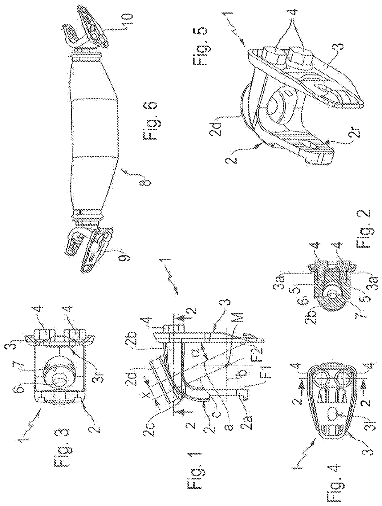
[0023]FIG. 1 shows a joint fork 1 according to the invention, which can preferably be used for a rear-axle steering system of a motor vehicle, i.e. for connection or attachment to an actuator. For this, reference is made to the document DE 10 2014 206 934 A1 by the present applicant, mentioned at the beginning. The joint fork 1 is made in two parts, i.e. it consists of two components, a forged component 2 that forms a basic body and a separately made sheet component 3. The two components 2, 3 are connected firmly to one another by fixing screws 4, so that from the basic body / forged component and the separate side plate a joint fork with two side plates, or to name them differently two arms, is formed. The forged component 2 has a first side plate 2a, a web 2b and a curved section 2c that connects the first side plate 2a and the web 2b, so that the forged component 2 is approximately L-shaped. The separate component 3 made as a sheet-metal component forms the second side plate 3. The...


PUM


Abstract

A joint fork (1) for connection to a joint. The joint fork having two side plates (2a, 3) that are arranged approximately parallel with one another, and each having a side plate surface (F1, F2). A web (2b) connects the side plates (2a, 3) with one another. A fixing bore (6) is arranged in the web (2b) and has a longitudinal axis (a). The joint forks (1) are coupled to an actuator. The side plate surfaces (F1, F2) form, with the longitudinal axis (a), an angle of inclination (α) and the angle of inclination (α) is in the range from 20° to 70°, in particular around 30°. The actuator is fitted with the joint forks (1).

Description

[0001]This application is a National Stage completion of PCT / EP2017 / 083216 filed Dec. 18, 2017, which claims priority from German patent application serial no. 10 2017 201 352.4 filed Jan. 27, 2017.FIELD OF THE INVENTION[0002]The invention relates to a joint fork for connection to a joint, and an actuator for a rear-axle steering system.BACKGROUND OF THE INVENTION[0003]From DE 10 2015 211 414 A1 by the present applicant, a joint fork for connection to an articulated rod, in particular a transverse control arm or track rod, is known. The joint fork has a web with a through-bore and two arms or side plates arranged parallel to one another, with a slight inclination. Inside the fork, i.e. between the two side plates, a joint in the form of a rubber mounting is arranged, which is connected to the track rod. Alternatively, a ball joint such as a ball sleeve joint could also be fitted there. The joint fork is connected to a screw-on or plug-in stud by means of a screw-bolt passing through...

Claims


Application Information

Patent Timeline
Patent Type & Authority Applications(United States)
IPC IPC(8): B60G7/00B62D7/16
CPCB60G2204/4302B62D7/16B60G7/006B60G2206/8207B60G2204/143F16C2326/24B60G2206/11
Inventor KUHNT, TORSTEN
Owner ZF FRIEDRICHSHAFEN AG
Why Eureka
Try Eureka