Eureka AIR delivers breakthrough ideas for toughest innovation challenges, trusted by R&D personnel around the world.

Leveling spacer device

a spacer and leveling technology, applied in flooring, construction, building construction, etc., can solve the problems of dead time of insertion, ineffective spacer function of the device itself, ruining the exposed surface of tiles, etc., and achieve the effect of saving tim

Active Publication Date: 2019-11-14
RAIMONDI
View PDF6 Cites 8 Cited by
  • Summary
  • Abstract
  • Description
  • Claims
  • Application Information

AI Technical Summary

Benefits of technology

The invention is a protection ring nut that prevents damage to tiled surfaces during installation. The ring nut is designed to rotate without sliding on the tiled surface, allowing for easy movement between the presser and the tiled surface. This prevents rubbing and ruining of the tiled surface while also ensuring a smooth installation process. The protection ring nut is simple to use and can be easily anchored to the presser, saving time and ensuring proper positioning. Overall, the invention provides an efficient and effective safeguard for the exposed surface of tiled surfaces during installation.

Problems solved by technology

The leveling spacer devices, in particular the screw-type spacers, have the drawback that the rubbing exerted by the presser on the exposed surface of the tiles, in the last tightening steps, can ruin the exposed surface of the tiles, scratching them.
Furthermore, the rubbing between the tiles and the presser can be relieved in the form of centrifugal force on the tiles themselves, which are therefore unevenly enlarged at the device itself, widening or deforming the gap between the tiles, actually making the spacer function of the device itself ineffective.
This ring nut, however, involves a dead time of insertion on the installed spacer leveling devices and an additional charge for the personnel assigned to the laying, which sometimes deliberately neglects the use thereof.
Moreover, this ring nut with shaped through hole with anti-rotation function occludes the sight of the gap at the device with the impossibility for the personnel in charge of the laying to verify whether excess adhesive has emerged at the device due to the exercise of the pressure on the presser and, therefore, to remedy it before the hardening of the adhesive.

Method used


Image

  • Leveling spacer device
  • Leveling spacer device
  • Leveling spacer device

Examples


Embodiment Construction

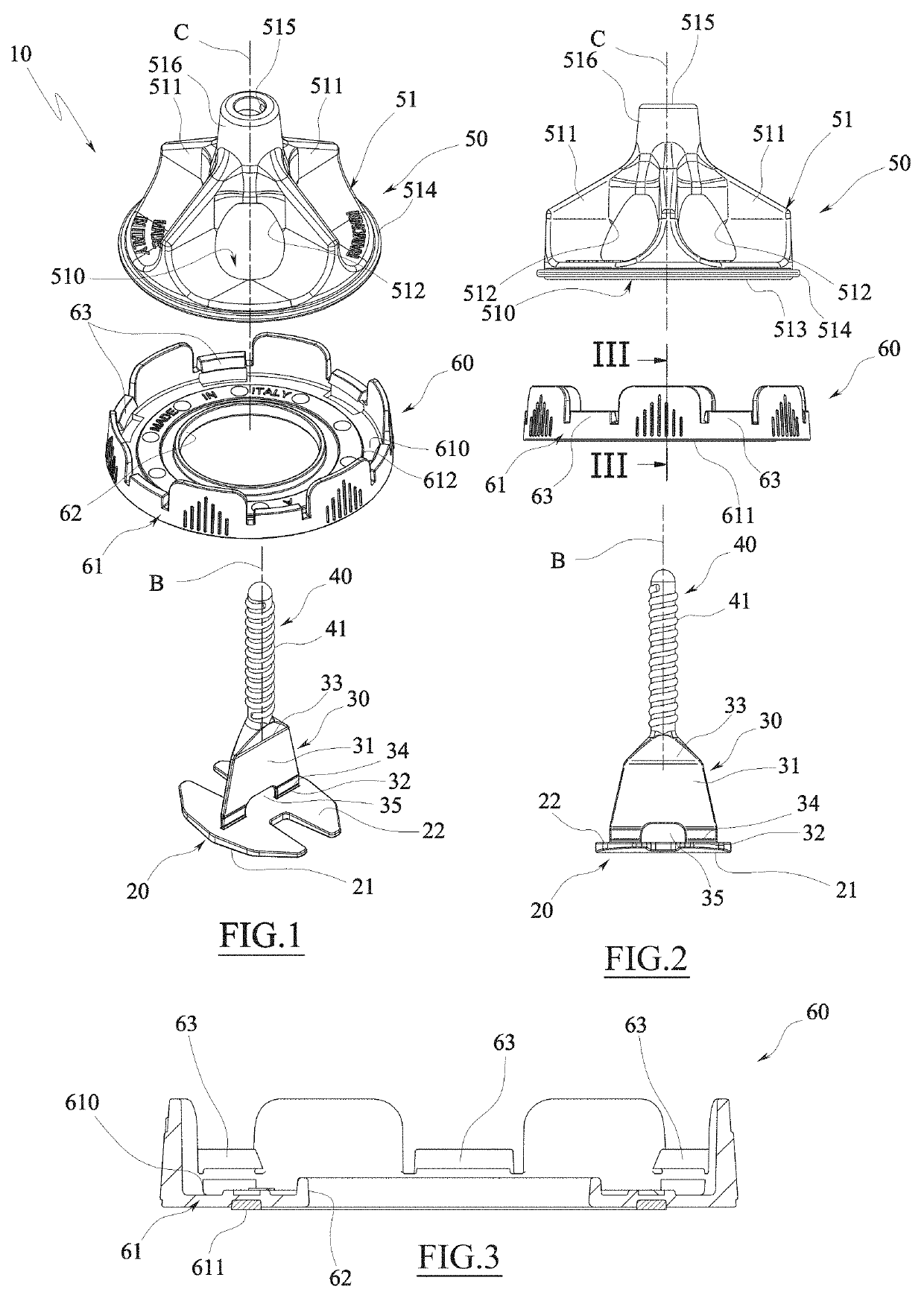
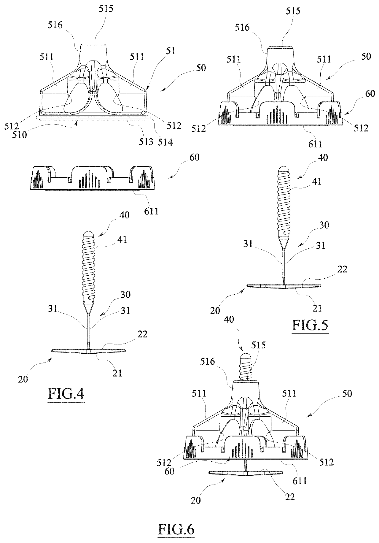
[0055]With particular reference to these figures, reference numeral 10 generally designates a leveling spacer device to facilitate the laying of sheet-like products, such as tiles and the like, generally indicated by the letter P, and suitable for coating surfaces, or flooring, walls, ceilings and the like.

[0056]Each tile P adapted to be laid to coat a surface has a wide laying surface P1, for example lower, and an opposite wide exposed surface P2, for example upper, preferably of homologous shape (for example polygonal, preferably quadrangular) with respect to the laying surface P1.

[0057]Each tile P then comprises a plurality of sides P3, generally angled relative to the laying surface P1 and the exposed surface P2, which delimit the tile itself laterally.

[0058]The device 10 comprises a base 20 which is adapted for use to be placed behind the laying surface P1 of the tiles P (shown only schematically in FIGS. 16a-16d).

[0059]The base 20 in the illustrated example has an enlarged sha...


PUM


Abstract

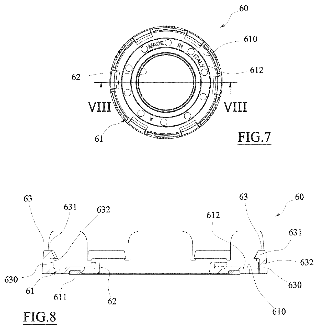
A leveling spacer device (10) for laying sheet-like products (P) for the coating of surfaces which comprises:a base (20), which may be positioned at the rear of a laying surface of at least two sheet-like products (P) being adjacent and placed side-by-side relative to a side-by-side direction (A);a separator element (30) rising from said base (20) angled relative thereto and suitable for sliding between the facing side walls of said two sheet-like products (P) placed side by side;a threaded stem (40) rising from the separator element (30) with a screw axis (B) orthogonal to the base (20);a presser (50) that can be screwed onto the threaded stem (40) andan anti-sliding protection ring nut (60) suitable for being interposed between the presser (50) and the base (20), wherein the protection ring nut (60) comprises a first surface (610) facing towards the presser (50) and configured to come into contact therewith and a second opposing surface (611) facing towards the base (20), wherein the second surface (611) has a sliding friction coefficient greater than a sliding friction coefficient of the first surface (610).

Description

TECHNICAL FIELD[0001]The present invention relates to a leveling spacer device for laying sheet-like products, such as tiles, slabs of natural stone or the like, for the coating of surfaces, such as surfaces that can be walked on, floors, wall or ceiling coatings and the like.PRIOR ART[0002]In the field of laying of tiles for coating surfaces, such as flooring, walls and the like, it is known to use spacer devices which, in addition to spacing the tiles, allow the planar arrangement thereof, that is, they are such as to place the exposed surface of the tiles substantially coplanar; these devices are commonly called leveling spacers.[0003]The known leveling spacer devices generally comprise a base, which can be positioned below the laying surface of at least two (three or four) adjacent tiles, from which at least one separator element rises, suitable to contact, through its lateral sides, the facing sides of the two (three or four) tiles to be placed next to each other on the laying ...

Claims


Application Information

Patent Timeline
Patent Type & Authority Applications(United States)
IPC IPC(8): E04F21/22E04F21/00
CPCE04F21/0092E04F21/22E04F15/02022E04F21/1877
Inventor SIGHINOLFI, RICCARDO
Owner RAIMONDI
Why Eureka
Eureka Blog
Learn More