
Projector configuration with subdivided optical aperture for near-eye displays, and corresponding optical systems

a projector and optical aperture technology, applied in the field of virtual reality and augmented reality displays, can solve the problem of low f-number of projector optics, and achieve the effect of reducing cross-talk

Active Publication Date: 2019-11-14
LUMUS LTD
View PDF13 Cites 31 Cited by
  • Summary
  • Abstract
  • Description
  • Claims
  • Application Information

AI Technical Summary

Benefits of technology

The present invention relates to a new projector configuration that reduces the size of the optical engine and improves optical performance with a small number of lenses. Additionally, a baffle arrangement is included to reduce cross-talk between the collimating optics of the projector.

Problems solved by technology

This results in a low f-number of the projector optics, often with f<1, and imposes corresponding strict requirements on the optical design and quality of the optical components.

Method used


Image

  • Projector configuration with subdivided optical aperture for near-eye displays, and corresponding optical systems
  • Projector configuration with subdivided optical aperture for near-eye displays, and corresponding optical systems
  • Projector configuration with subdivided optical aperture for near-eye displays, and corresponding optical systems

Examples


Embodiment Construction

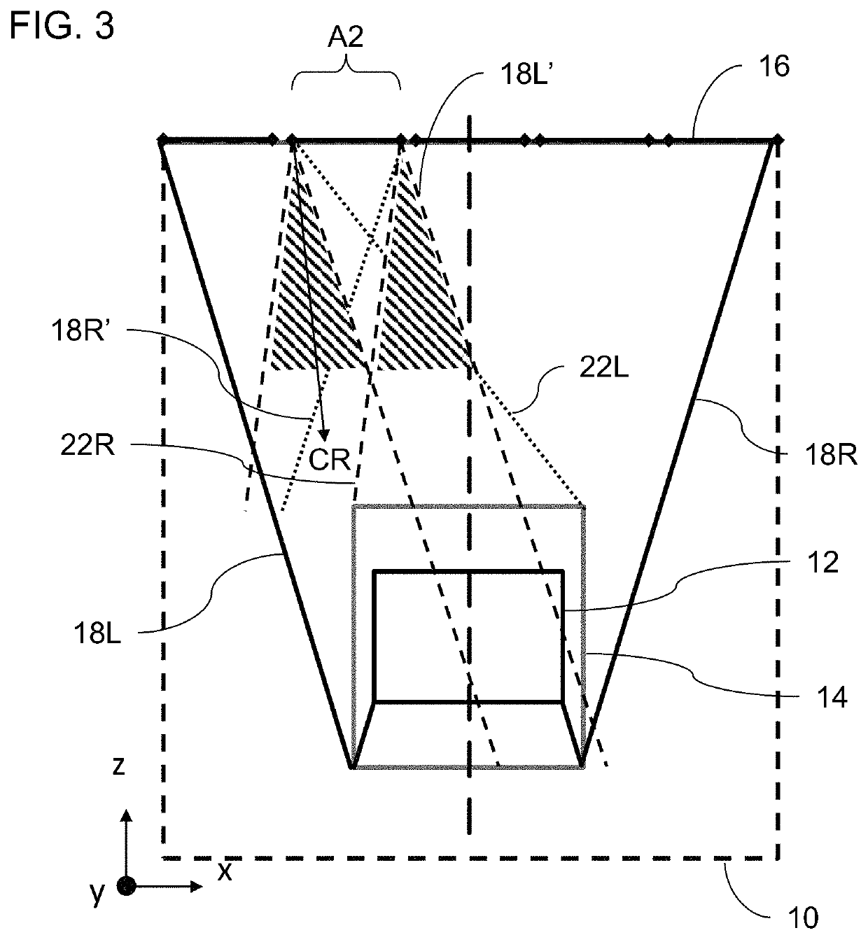
[0041]The present invention provides a projector configuration and corresponding optical system for virtual reality and augmented reality head-up displays, particularly useful in near-eye displays, in which an optical aperture of an image projection system is partitioned (subdivided) into several zones, each with its own image generating and / or illumination sub-system.

[0042]The principles and operation of projectors and optical systems according to the present invention may be better understood with reference to the drawings and the accompanying description.

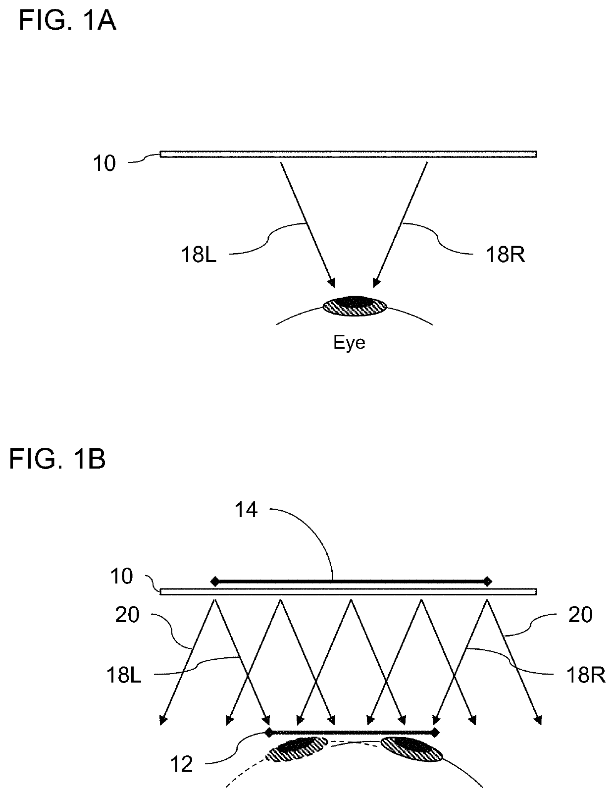
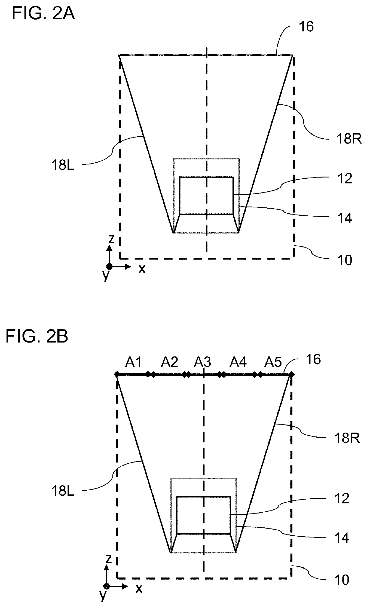
[0043]By way of introduction, referring to FIGS. 1A, 1B and 2A, a display based on a light-guide optical element (LOE) 10 is typically designed to provide the full field of view from a right-most ray 18R to a left-most ray 18L to the eye of the viewer over the entirety of an “eye motion box” (EMB) 12 corresponding to the acceptable range of eye positions. FIG. 1A illustrates the field of view that is provided to the eye in a cent...


PUM


Abstract

An optical system for displaying a projected image to an observer includes a light-guide optical element having two major parallel surfaces and configured for guiding illumination corresponding to a projected image collimated to infinity by internal reflection at the major parallel surfaces from a coupling-in region to a coupling-out region where at least part of the illumination is coupled out towards an eye of the observer, and a projector configuration associated with the coupling-in region of the light-guide optical element. The projector configuration includes a number of adjacent optical arrangements, each including collimating optics deployed for projecting a subset of the illumination. The adjacent optical arrangements cooperate to provide an entirety of the projected image to the coupling-out region.

Description

FIELD AND BACKGROUND OF THE INVENTION[0001]The present invention relates to virtual reality and augmented reality displays and, in particular, it concerns a projector configuration for such displays in which an overall optical aperture for projection of an image into a light-guide optical element is subdivided into a number of separate smaller apertures.[0002]Many virtual reality and augmented reality displays employ a light-guide optical element (LOE) with two major parallel planar surfaces within which an image propagates by internal reflection. Illumination corresponding to a collimated image is introduced into the LOE at a coupling-in region, typically at one side, and propagates within the LOE by internal reflection until reaching a coupling-out region where it is coupled out of the LOE towards the viewer's eye. Coupling out of the illumination toward the eye may be by use of a set of obliquely angled partially reflective internal surfaces, such as described in U.S. Pat. Nos. 6...

Claims


Application Information

Patent Timeline
Patent Type & Authority Applications(United States)
IPC IPC(8): F21V8/00
CPCG02B6/0035G02B6/003G02B27/0172G02B2027/0123G02B3/005
Inventor EISENFELD, TSION
Owner LUMUS LTD
Learn More