Flow stopping tool for pipelines

Active Publication Date: 2019-11-21
J VAN BEUGEN BEHEER BV
View PDF0 Cites 3 Cited by
  • Summary
  • Abstract
  • Description
  • Claims
  • Application Information

AI Technical Summary

Benefits of technology

This patent is for a shock absorber that can be used with a flow stopping tool for pipelines. The shock absorber is designed to prevent leaking of the medium used to inflate the balloon-like element. It includes a secured coupler that connects the shock absorber with the hose, allowing for easy installation. The technical effects of this patent are improved sealing of the shock absorber and hose, making it more robust and reliable, and compatibility with existing flow stopping tools.

Problems solved by technology

As a consequence, the hose may get damaged which may result in a leakage of the medium that is used for inflating the balloon-like element.
In a worst-case scenario, the balloon-like element may be completely ruptured from the hose and will get lost in the pipeline.
The construction of joint and springs facilitate insertion of the balloon into a pipeline, but does not strengthen the connection between the pressure rod and the balloon.
Such an internal guiding shaft does not strengthen the connection between the pressure rod and the balloon.

Method used


Image

  • Flow stopping tool for pipelines
  • Flow stopping tool for pipelines
  • Flow stopping tool for pipelines

Examples


Embodiment Construction

[0036]It will be appreciated that for simplicity and clarity of illustration, where considered appropriate, reference numerals may be repeated among the figures to indicate corresponding or analogous elements or steps. In addition, numerous specific details are set forth in order to provide a thorough understanding of the embodiments described herein. However, it will be understood by those of ordinary skill in the art that the embodiments described herein may be practiced without these specific details. Furthermore, this description is not to be considered as limiting the scope of the embodiments described herein in any way, but rather as merely describing the implementation of the various embodiments described herein.

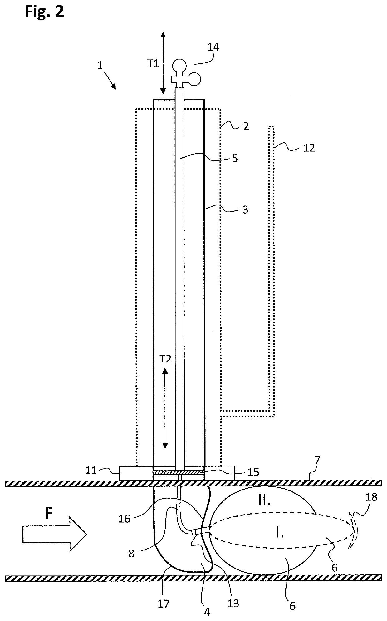
[0037]With reference to FIG. 1, a prior-art flow stopping tool 1 is shown. The flow stopping tool 1 comprises an external dome 2, a moveable lance 3 that can move within external dome 1. Movable lance 3 comprises an insertion shoe 4 and a moveable pressure rod 5 with ...


PUM


Abstract

A flow stopping tool for pipelines is disclosed, wherein the flow stopping tool comprises an inflatable balloon-like element that is in connection to a pressure rod. A hose is used for inflating the balloon-like element with a gas or a fluid, such that the balloon-like element can block a flow in a pipeline. A first end of the hose is in connection to the pressure rod and a second end of the hose is in connection to the balloon-like element. A part connecting the hose with the inflatable balloon-like element, but outside said balloon-like element, comprises a shock absorber for securing the hose-balloon connection.

Description

TECHNICAL FIELD[0001]The present invention relates to flow stopping tools for live maintenance and new construction operations on pipelines.BACKGROUND ART[0002]Pipelines are essential for urban and industrial applications. For example, pipelines are used for the transportation of liquids or gases below and above the ground or sea. These type of pipelines typically have operating pressures larger than 8 bar (120 psi). Other type of pipelines are distribution or utility pipelines with typical operating pressures smaller than or equal to 8 bar (120 psi) and are commonly used for the distribution of gasses and liquids to end users such as living quarters and industrial areas. In case a section of a transportation or distribution pipeline needs to be isolated, for example to facilitate maintenance work, repairs or the insertion of tee's or branches, it is necessary to stop the flow in the pipeline. Flow stopping tools are typically used for these type of operations as they allow an opera...

Claims


Application Information

Patent Timeline
IPC IPC(8): F16L55/124
CPCF16L55/124F16K7/10F16L55/134
Inventor VAN BEUGEN, LEONARDCORIC, ENVER
Owner J VAN BEUGEN BEHEER BV
Why Eureka
Try Eureka