Method of machining a groove

a groove and groove technology, applied in the direction of cutting inserts, manufacturing tools, tool holders, etc., can solve problems such as vibrations

Active Publication Date: 2019-11-28
SANDVIK INTELLECTUAL PROPERTY AB
View PDF10 Cites 5 Cited by
  • Summary
  • Abstract
  • Description
  • Claims
  • Application Information

AI Technical Summary

Benefits of technology

[0048]By arranging the third and fourth surfaces of the blade portion paralle

Problems solved by technology

The inventors have found that the in state of the art methods, vibra

Method used


Image

  • Method of machining a groove
  • Method of machining a groove
  • Method of machining a groove

Examples


Embodiment Construction

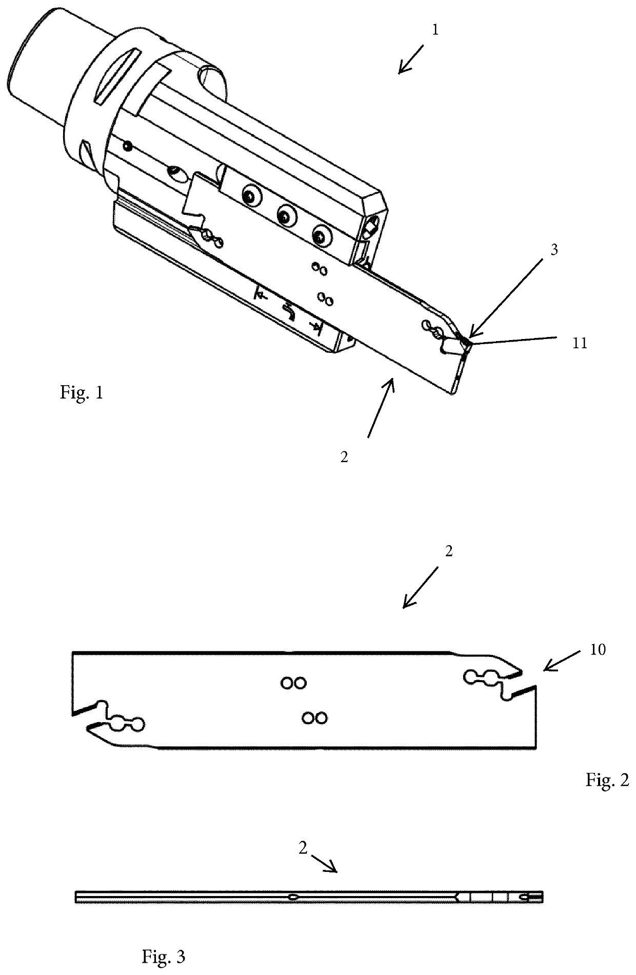
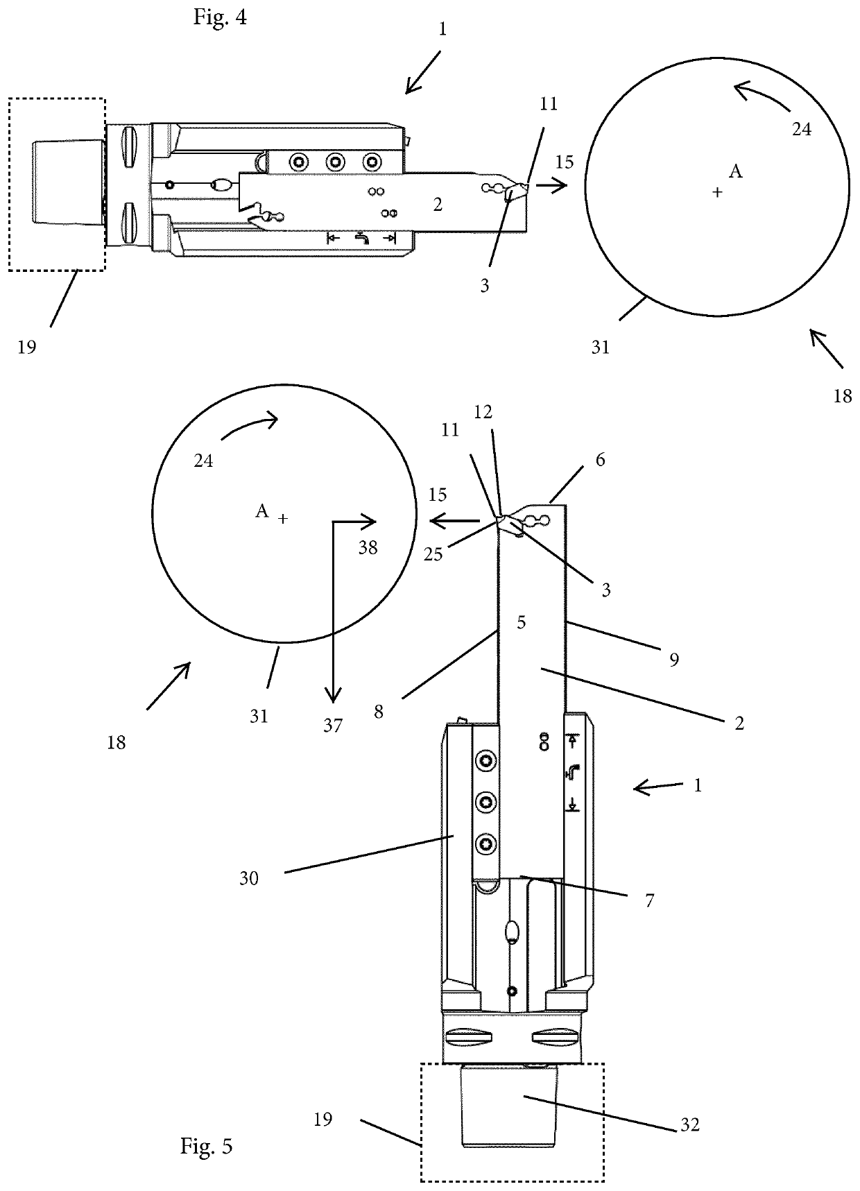
[0074]Reference is made to FIGS. 1-4 which show a state of the art grooving tool 1, a state of the art blade portion 2, a state of the art insert 3 mounted in an insert seat 10 of the blade portion 2. During a cutting operation, such as a grooving or parting or cutting-off operation, the grooving tool 1 is connected to a machine interface 19 and moved in a feed direction 15 towards a rotational axis A of a metal work piece 18. The work piece 18 rotates around the rotational axis A thereof in a rotational direction 24. A main cutting edge 11 of the insert 3 cuts a groove in the peripheral surface 31 of the work piece 18. A tangential cutting force (not shown) is directed downwards in FIG. 4.

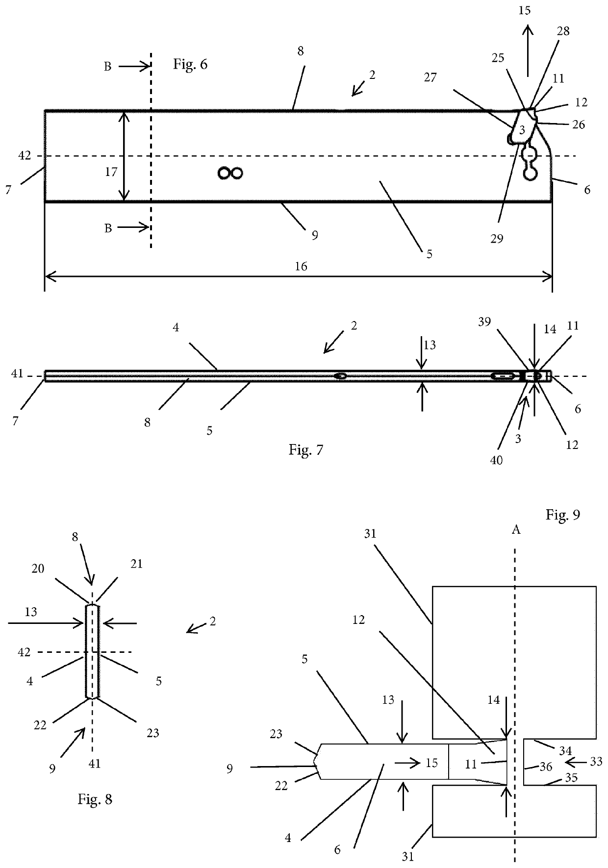
[0075]Reference is now made to FIG. 5-9, which show a blade portion 2 according to a first type and a method according to an embodiment. The grooving tool 1 comprises a blade portion 2 having a constant or substantially constant blade width 13, and an insert 3 having a maximum insert width 14 defi...


PUM

PropertyMeasurementUnit
Forceaaaaaaaaaa
Widthaaaaaaaaaa
Distanceaaaaaaaaaa

Abstract

A method for cutting a groove of a predetermined groove width in a work piece, including the steps of providing a metallic work piece having a peripheral surface; providing a grooving tool including a blade portion having a constant or substantially constant blade width, and an insert having a maximum insert width defined by a main cutting edge; selecting the insert width to be greater than the blade width; connecting the grooving tool to a machine interface of a machine tool; rotating the work piece about a rotational axis thereof in a rotational direction; and cutting a groove in the work piece by moving the tool in a feed direction towards the rotational axis of the work piece, such that the groove width is equal to or substantially equal to the insert width and such that a tangential cutting force is directed towards or substantially towards the machine interface.

Description

TECHNICAL FIELD OF THE INVENTION[0001]The present invention belongs to the technical field of metal cutting tools. More specifically the present invention belongs to the field of methods for cutting a groove of a predetermined groove width in a work piece, Such machining can be made using computer or computerized numerical control, i.e. CNC, machines.BACKGROUND OF THE INVENTION AND PRIOR ART[0002]The present invention refers to methods for cutting a groove of a predetermined groove width in a work piece. More specifically, the present invention relates to a turning method, using a cutting tool comprising a replaceable cutting insert, more specifically a parting, cutting-off or grooving insert.[0003]Metal cutting parting-off, cutting-off or deep grooving, have long been known to be a difficult operation. Chip jamming have been known to be one problem. One other problem is vibrations, causing risk of tool breakage and poor surface finish, among other things. Such an operation and cutt...

Claims


Application Information

Patent Timeline
IPC IPC(8): B23B27/08B23B29/04
CPCB23B29/043B23B2220/12B23B27/086B23B2205/02
Inventor LUNDSTROM, STAFFANANDERSTEDT, JOHAN
Owner SANDVIK INTELLECTUAL PROPERTY AB
Why Eureka
Try Eureka