Ratchet wrench

Inactive Publication Date: 2019-11-28
YANG CHUN WEI +1
View PDF16 Cites 0 Cited by
  • Summary
  • Abstract
  • Description
  • Claims
  • Application Information

AI Technical Summary

Benefits of technology

[0012]The primary objective of the present invention is to provide a ratchet wrench wherein the first and second recesses b

Problems solved by technology

However, the cavity includes a closed top and a closed bottom, so that only T-shaped blade can be used to make the cavity when manufacturing the head of the wrench.
The T-shaped blade is an expensive tool and th

Method used


Image

  • Ratchet wrench
  • Ratchet wrench
  • Ratchet wrench

Examples


Example

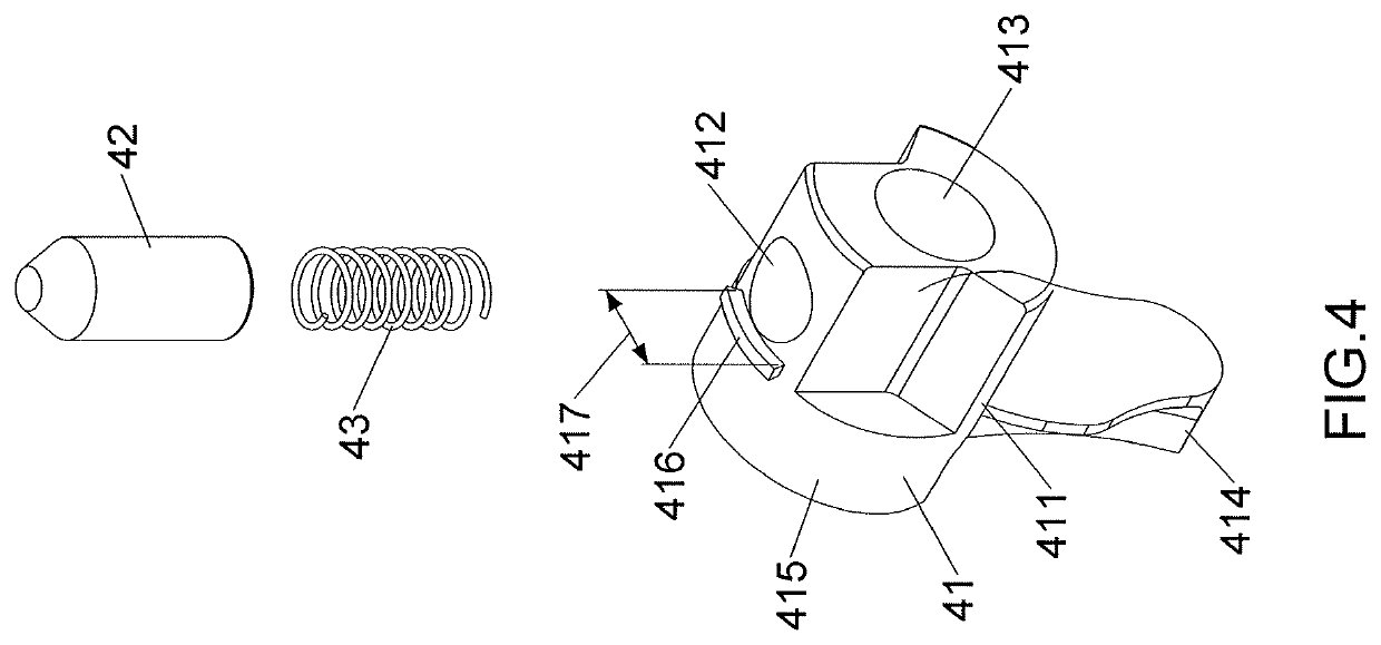
[0041]As shown in FIG. 13 which shows the second embodiment, wherein the switch member 41 does not have the ridge 416, and the ring 50 contacts the cap 42 to pivotably connect the switch unit 40 to the second recess 13.

Example

[0042]As shown in FIG. 14 which shows the third embodiment, wherein the body 10 is connected on a first end of a handle 100. The second end of the handle 100 is defined a penetrating hole 101 thereon for mounting on a hanging member, an upper face and a lower face are defined on the second end of the handle 100, and the upper face and the lower face of the handle are defined a plurality of dents 102 symmetrically thereon.

Example

[0043]As shown in FIGS. 15 and 16, which shows the fourth embodiment, wherein the top end of the ratchet wheel 20 has a polygonal recessed connecting portion 22. The polygonal recessed connecting portion 22 including a first receiving recess 220 and a second receiving recess 221 coaxially, the diameters of the first receiving recess 220 and the second receiving recess 221 are different for mounting with workpieces in different sizes respectively.


PUM


Abstract

A ratchet wrench includes at least one ratchet mechanism. The at least one ratchet mechanism comprises a body, a ratchet wheel, a pawl, a switch unit, a ring and a top clip. The body includes a through hole, a first recess, a second recess and a top recessed area to accommodate the ratchet wheel, the pawl, the switch unit, the ring and the top clip. The ratchet wheel has a first pivotal portion, a top groove, a second pivotal portion and a restricting protrusion. The switch unit is pivoted to control the movement of the pawl in the first recess. The ring is located in the top recessed area and has a fourth pivotal portion connected to the first pivotal portion. The top clip and the restricting protrusion on two ends of the ratchet wheel restrict the ring and the ratchet wheel in the through hole.

Description

[0001]The present invention is a Continuation-In-Part application of applicant's former application with the application Ser. No. 15 / 424,761, filed on Feb. 3, 2017, and Ser. No. 15 / 450,021 filed on Mar. 5, 2017.BACKGROUND OF THE INVENTION1. Fields of the Invention2. Descriptions of Related Art[0002]The conventional ratchet wrench known to applicant is disclosed in U.S. Pat. No. 6,282,992, and comprises a handle; a head extended from the handle and including a hole, a web being defined between the handle and the head, a cavity being defined in the web and communicated with the hole, the web further including a compartment having a first end communicated with the cavity and a second end communicated with outside, thereby leaving a bridge in the web; a drive member rotatably mounted in the hole of the head, the drive member including a plurality of teeth formed on an outer periphery thereof; a pawl mounted in the cavity and including a first side with a plurality of ratchet teeth for r...

Claims


Application Information

Patent Timeline
IPC IPC(8): B25B13/46B25B23/00
CPCB25B13/463B25B23/0028
Inventor YANG, CHUN-WEIZHANG, ZHE-PING
Owner YANG CHUN WEI
Why Eureka
Try Eureka