
Spectacle frame with temple orientation according to a plurality of planes

a technology of planes and spectacles, applied in the field of spectacle frames, can solve the problems of oversizing either of the spectacle temples, affecting the orientation of the temples, and deformation of the front face, and achieve the effect of stable positioning of the temple relative and efficient frame holding

Active Publication Date: 2019-11-28
NIKKOR +1
View PDF0 Cites 1 Cited by
  • Summary
  • Abstract
  • Description
  • Claims
  • Application Information

AI Technical Summary

Benefits of technology

The invention ensures a stable positioning of a temples relative to the front face, but it also allows the temples to be opened in the horizontal plane for increased comfort and a better hold on the wearer. The technical effect is improved comfort and efficient holding of the frame on the wearer.

Problems solved by technology

Another problem encountered with spectacle frames is their relative fragility to shocks and other incidental mechanical stress, capable of resulting in a deformation of the front face and an alteration of the parallelism between the temples and their respective position relative to the front face.
Whatever the elements implemented to reach such a double degree of liberty of angular motion of the spectacle temples, it can be observed that the means for reaching such a result are relatively complex to implement, and tend to increase the weight of the actual frame, generating an oversizing either of the spectacle temples, or of the lugs coming out of the front face, and thus of the actual front face.
Further, known prior art devices only allow a limited angular motion of the spectacle temples in the plane called transverse.
Further, another technical problem has to do with the stability of the temple with respect to the front face of the frame, when said temple is in open position, that is, enabling a user to wear the frame.

Method used


Image

  • Spectacle frame with temple orientation according to a plurality of planes
  • Spectacle frame with temple orientation according to a plurality of planes
  • Spectacle frame with temple orientation according to a plurality of planes

Examples


first embodiment

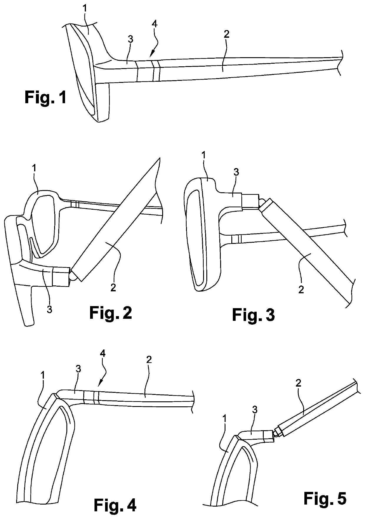
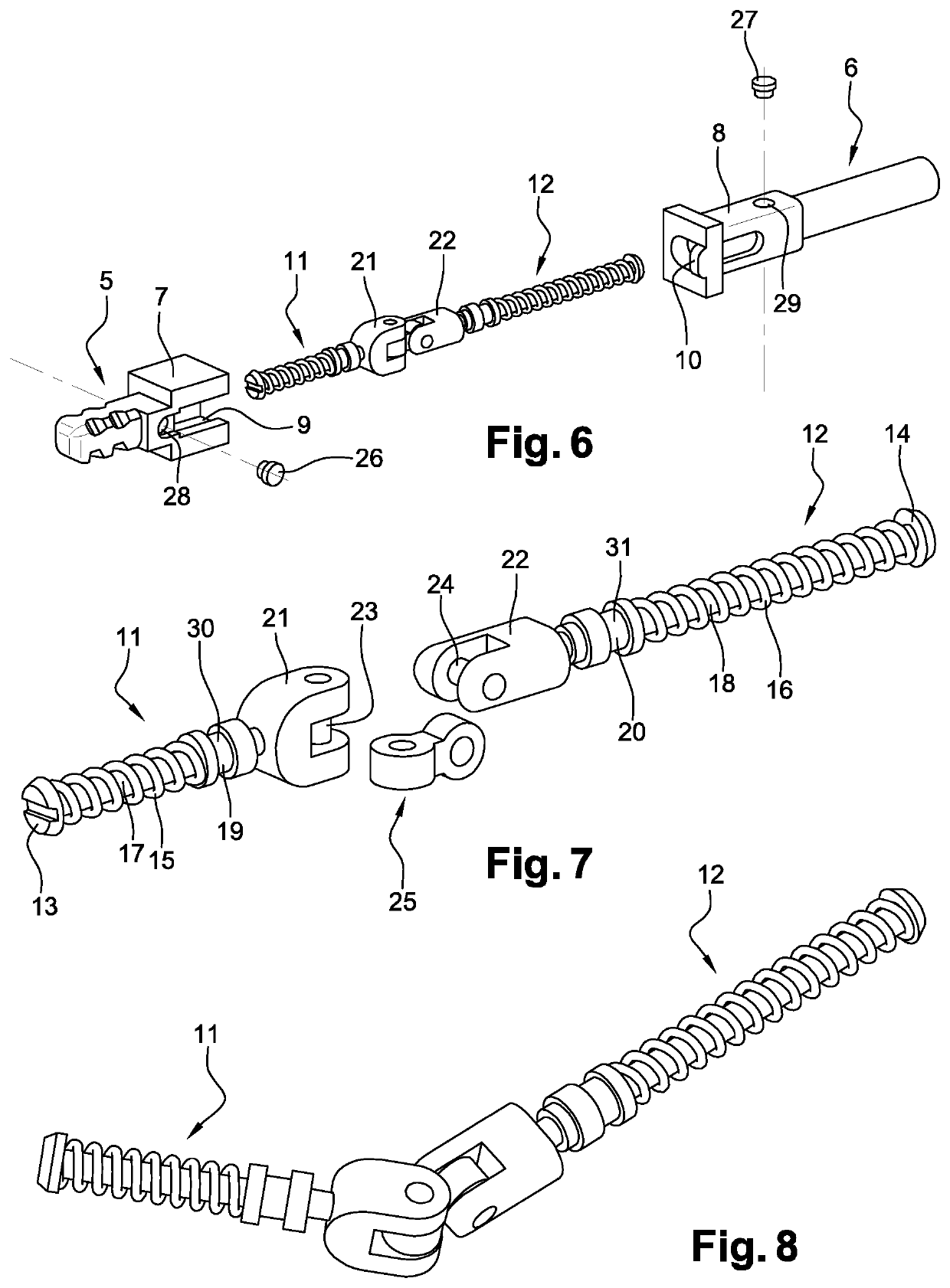
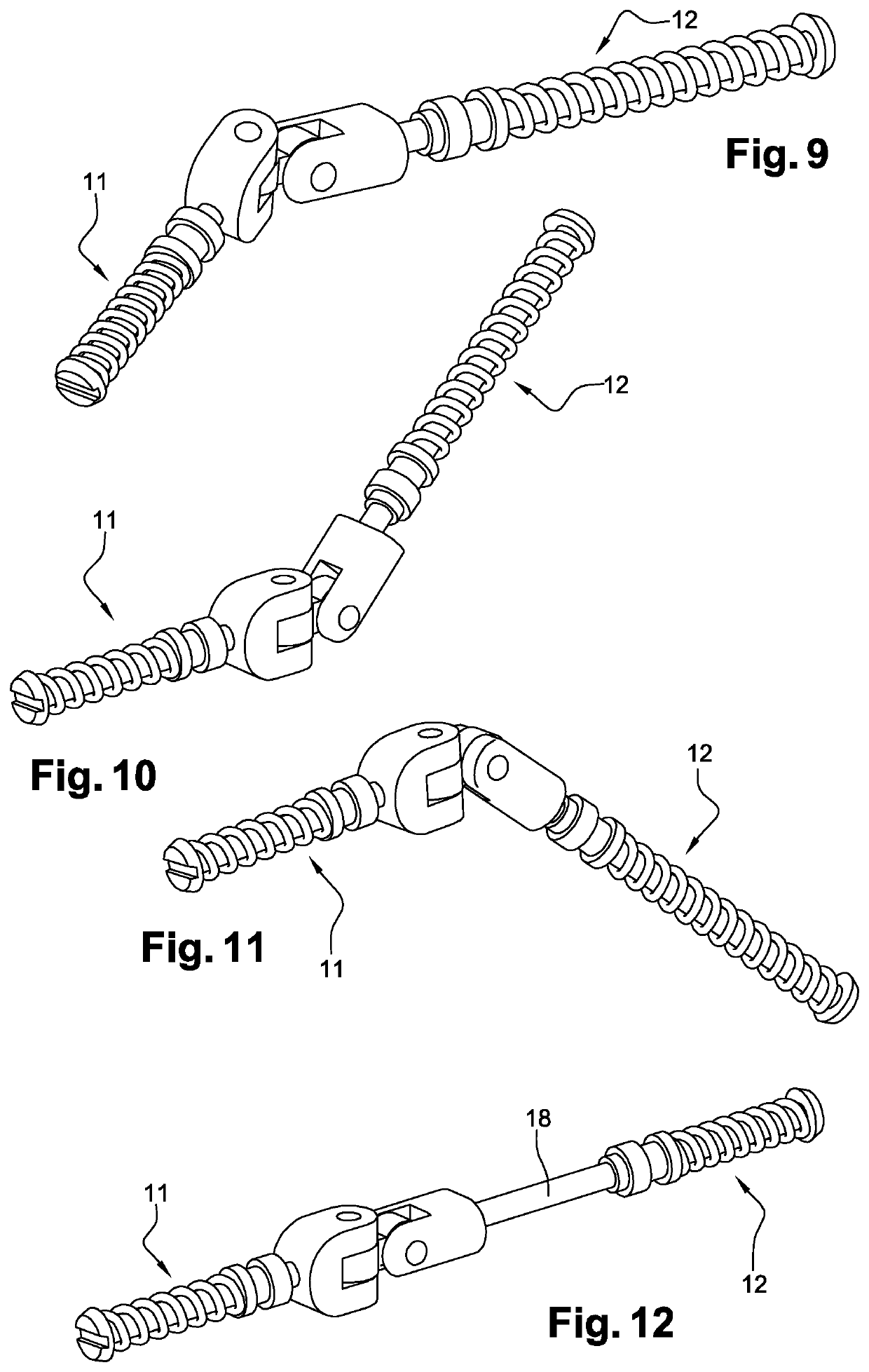
[0049]One of the aspects has been shown in FIGS. 6 and 7. Basically, hinge 4 is first formed of attachment members, respectively 5 in lug 3, and 6 in temples 2, typically made of metal, or even of a composite material.

[0050]Such attachment members are intended to be rigidly connected to lug 3 and to frame 2. Such a rigid connection may be achieved in different ways: screwing, gluing, snapping or also overmolding.

[0051]Their free ends (respectively 7 and 8) have, as can in particular be observed in FIG. 6, a substantially parallelepipedal shape. The free ends terminate in a planar surface, intended to come into contact with each other when the branch is in open or stable position (such as shown in FIG. 1) and such as it has actually been shown in FIGS. 18 and 19.

[0052]One of the lateral faces of free end 7 of the attachment member of lug 5 has a recess 9, in the case in point formed by an elongated opening intended to cooperate with a protrusion 10, emerging from free end 8 of attach...

second embodiment

[0073]A second embodiment has been shown in relation with FIGS. 24 to 37. Basically, the operation according to the second embodiment is identical to that of the previously-described first embodiment.

[0074]However, to simplify the members involved, on the one hand, and, accordingly, to limit the bulk generated by the hinge assembly, and to stabilize the orientation of the temples with respect to the front face of the frame on the other hand, some of said members undergo modifications, described hereafter in further detail.

[0075]Thus, to begin with, the sliding rings 19 and 20 of the first embodiment are respectively replaced, on the one hand:

[0076]with a plate 33 integrated within free end 7 of attachment member 5 rigidly connected to the front face of the frame, said plate being pierced with a through opening within which rod 17 of the corresponding hinging member 11 is capable of sliding, said plate 33 extending perpendicularly towards said front face, the extension receiving a sc...


PUM


Abstract

A spectacle frame including a front face for supporting the lenses and temples connected to the front face by means of hinges, each including an attachment member, respectively rigidly connected to the front face and to the temples, each receiving a hinging member, having its free end provided with a hinge pin, said hinge pins being perpendicular to each other. The attachment members are hollow and define a cylindrical sheath. The hinging members each include a rod, intended to be received in the respective sheath, one of the ends of the rod being provided with an abutment and the other end being provided with said hinge pin, each of the rods receiving a sliding ring submitted to the action of a spring bearing against the abutment, said ring being rigidly connected to the corresponding attachment member near the free end thereof. The hinge pins of the hinging members are rigidly connected to each other by means of a connection member.

Description

TECHNOLOGICAL FIELD[0001]The present disclosure concerns the field of spectacle frames.[0002]More specifically, the disclosure relates to a spectacle frame having temples which may be oriented and in particular displaced according to at least two different planes.BACKGROUND[0003]Conventionally, a spectacle frame is formed of a front face, receiving the optical or solar lenses, the front face being substantially oriented in a vertical plane when the frame is being worn by a user. Temples are hinged on the front face, so that said temples can be opened, to allow the positioning of the frame on the wearer's face, and, as a corollary, the closing or the folding back of the temples against said front face, in particular to enable to store the frame in a pocket or in a case.[0004]To increase the wearer's comfort and the proper holding of the frame on the wearer's face, and, as a corollary, to optimize the mechanical resistance of the frame, it is known to provide said temples with some re...

Claims


Application Information

Patent Timeline
Patent Type & Authority Applications(United States)
IPC IPC(8): G02C5/22
CPCG02C2200/30G02C5/2236G02C5/2263
Inventor SONTHONNAX, ALEXANDREKIMURA, TATSURO
Owner NIKKOR
Learn More