
Container-handling installation and method for conveying functional elements in a container-handling installation for the purpose of handling containers

a technology for container handling and installation, which is applied in the direction of non-mechanical conveyors, conveyor parts, transportation and packaging, etc., can solve the problem of comparatively low manufacturing cost of container handling installation, and achieve the effect of high flexibility and movable inexpensively in construction and operation

Active Publication Date: 2019-12-05
KRONES AG
View PDF13 Cites 1 Cited by
  • Summary
  • Abstract
  • Description
  • Claims
  • Application Information

AI Technical Summary

Benefits of technology

The present invention aims to provide a container-handling installation and a method for conveying functional elements in a container-handling installation for handling containers. The technical effects include precise control and flexibility of functional elements, low wear and adjustable flexibility to production requirements, and a simple and cost-effective structure. Additionally, the combination of conveying elements and magnetic force units simplifies maintenance and reduces maintenance costs. The described configuration helps in organizing changeover time or maintenance of the container-handling installation as simple and fast as possible, minimizing dowimes and production losses.

Problems solved by technology

As a result, the manufacturing costs for the container-handling installation are comparatively low.

Method used


Image

  • Container-handling installation and method for conveying functional elements in a container-handling installation for the purpose of handling containers
  • Container-handling installation and method for conveying functional elements in a container-handling installation for the purpose of handling containers
  • Container-handling installation and method for conveying functional elements in a container-handling installation for the purpose of handling containers

Examples


third embodiment

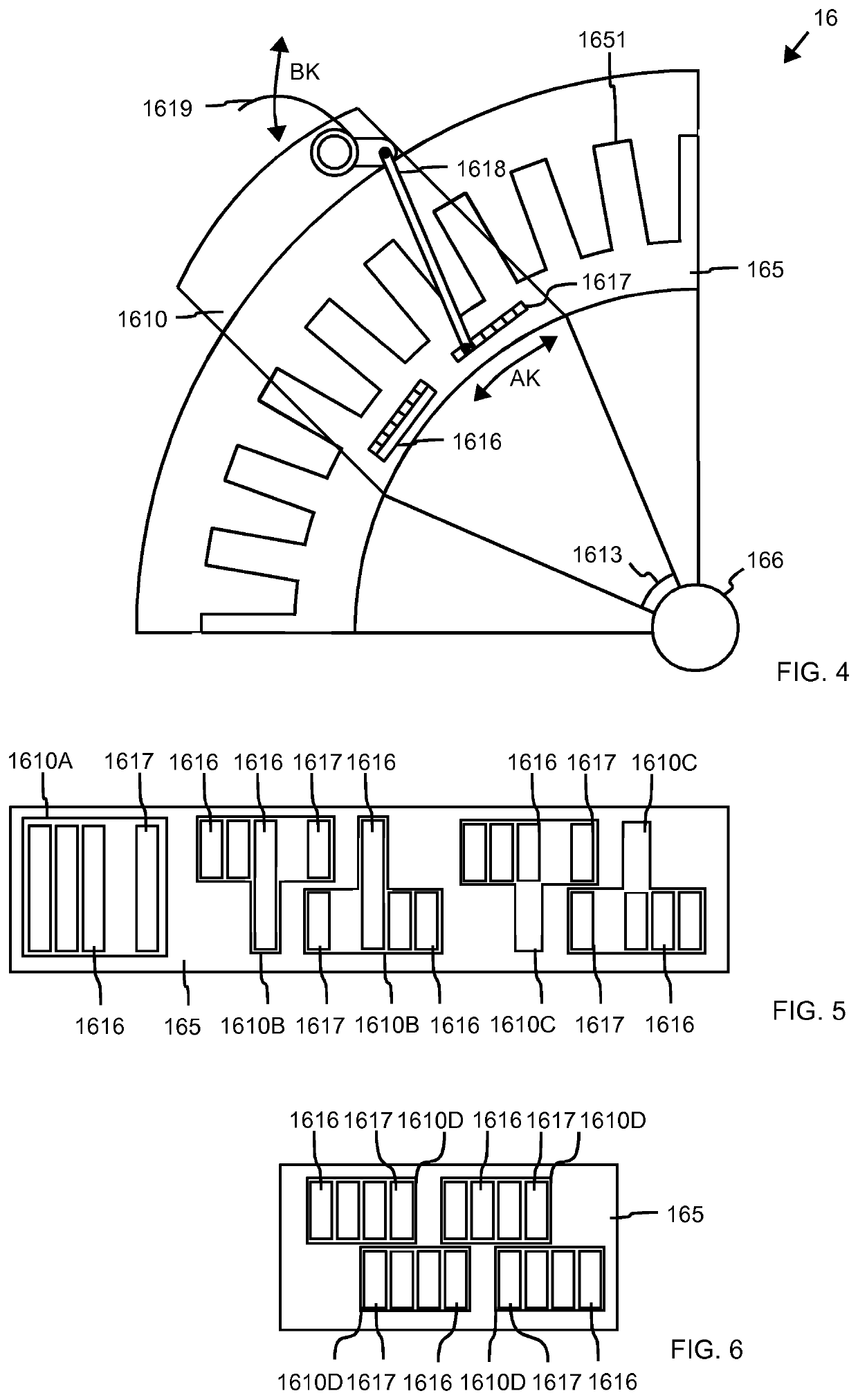
[0077]FIG. 7 illustrates the structure of a conveying element 1620 according to a For this purpose, FIG. 7 very schematically shows a part of the motor 16 in a plan view of the conveyance path magnetic force units 1651 on the outer circumference of the motor 16. FIG. 8 schematically shows a corresponding plan view of the motor 16.

[0078]The conveying element 1620 is largely carried out in the same way as the conveying element 161 or the conveying elements 162, 163 according to the first embodiment. Therefore, only the differences from the first embodiment will be described below.

[0079]The conveying element 1620 has a magnetic force unit with three first magnetic force elements 1626 and a second magnetic force element 1627. The second magnetic force element 1627 is disposed on a lever 1628, which is pivotally held on the conveying element 1620. The lever 1628 may be connected to the conveying element 1620 with a functional element 1629 shown here only very schematically. Within the c...

fourth embodiment

[0086]FIG. 10 illustrates the structure of a conveying element 1630 according to a The conveying element 1630 is largely carried out in the same manner as the conveying element 1620 according to the previous embodiment, however, the conveying element 1630 additionally has a second lever 1628 with a magnetic force element 1627, wherein the second lever 1628 is configured in the same manner as the first lever 1628 with magnetic force element 1627.

[0087]As a result, in a positioning between two conveyance paths 165 of different motors 16 in the so-called double combing mode, the conveying element 1630 can execute functions with a functional element on both sides of the conveying element 1630, as described above with respect to the preceding exemplary embodiments.

[0088]Optionally, the conveying element 1630 has a piezo motor 1639, via which actions can be performed with an electrically operated working element or functional element. For this purpose, the piezo motor is driven by induct...


PUM


Abstract

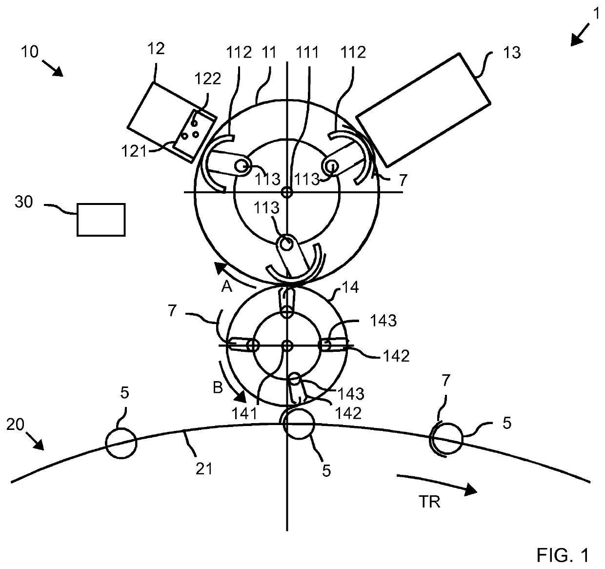
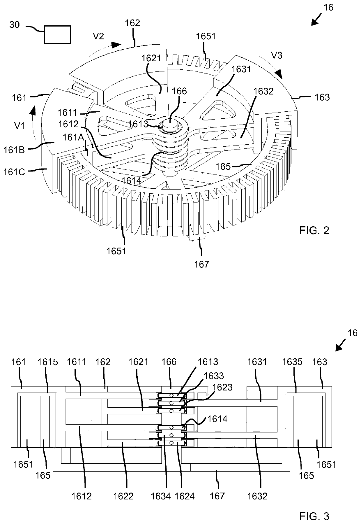
A container-handling installation and a method for conveying functional elements in a container-handling installation (1) for the purpose of handling containers is provided. The container-handling installation comprises at least two conveying elements which each have at least one functional element provided for the purpose of handling containers. A conveyance path is provided for conveying the at least two conveying elements one after the other, and independently of one another, along the conveyance path and by means of conveyance-path magnetic-force units, which are arranged along the conveyance path and at least some of which can be activated separately in order to interact with at least one magnetic-force unit of the respective conveying element A bearing unit is provided for each conveying element for the purpose of bearing the conveying element such that the at least two conveying elements are mounted on a common shaft.

Description

CROSS-REFERENCE TO RELATED APPLICATIONS[0001]This application a 371 National Stage application of International Application No. PCT / EP2017 / 075017 filed on Oct. 2, 2017, which claims foreign priority to German (DE) Application Serial No. 10 2017 101 331.8 filed on Jan. 24, 2017, the contents of both of which are incorporated herein by reference in their entireties.BACKGROUND OF THE INVENTIONField of the Invention[0002]The present invention relates to a container-handling installation and a method for conveying functional elements in a container-handling installation for handling containers, such as conveying containers, ejecting containers from a holding and / or conveying device; gripping labels for containers, labeling containers, etc.Description of the Prior Art[0003]Container-handling installations are used for handling containers, such as bottles, cans, etc., in order to prepare the containers for receiving a product, such as a beverage, a detergent, a cosmetic product, a piece go...

Claims


Application Information

Patent Timeline
Patent Type & Authority Applications(United States)
IPC IPC(8): B65G47/92B65G29/00
CPCB65G29/00B65G47/92B65G54/02B65G47/84
Inventor NEUBAUER, MICHAEL
Owner KRONES AG
Learn More