Blower fan

Active Publication Date: 2019-12-05
RINNAI CORP
View PDF0 Cites 0 Cited by
  • Summary
  • Abstract
  • Description
  • Claims
  • Application Information

AI Technical Summary

Benefits of technology

[0019]The washer with such a shape will not locally firmly press the vibration isolator when rotating toge

Problems solved by technology

However, the rotational shaft of the motor and the impeller are in direct solid contact (or indirect solid contact w

Method used


Image

  • Blower fan
  • Blower fan
  • Blower fan

Examples


Example

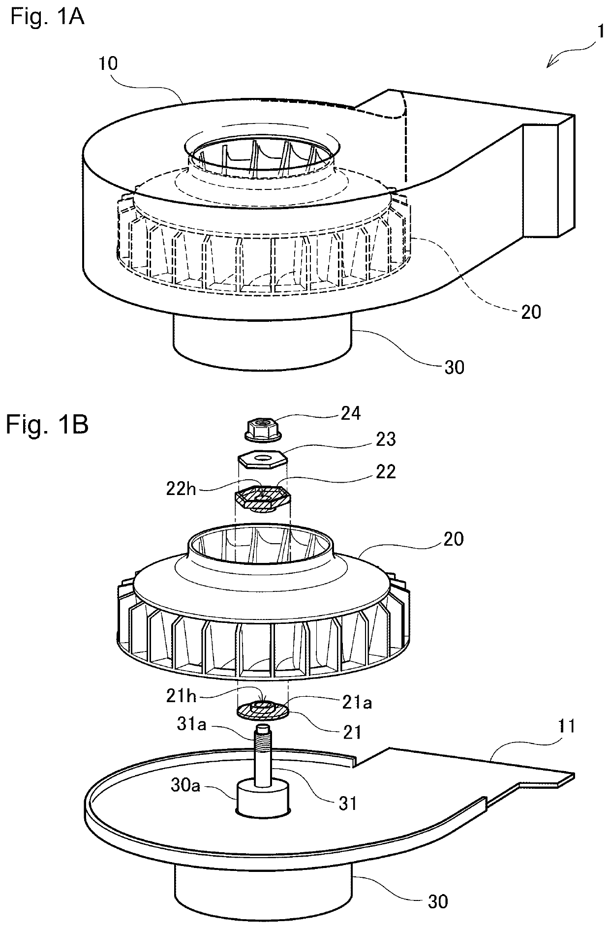
[0028]FIGS. 1A and 1B are perspective views of a blower fan 1 according to the present embodiment showing its structure. As shown in FIG. 1A, the blower fan 1 according to the present embodiment includes an impeller 20 accommodated in a body case 10, and a motor 30 mounted externally to the body case 10. The impeller 20 in the body case 10 is rotatable by the motor 30.

[0029]FIG. 1B is a diagram describing the impeller 20 being assembled to the motor 30 in the blower fan 1. In FIG. 1B, the upper portion of the body case 10 is not shown. As shown in FIG. 1B, the motor 30 has a protrusion 30a extending through the center of a bottom plate 11 of the body case 10, and a rotational shaft 31 extending from the center of the protrusion 30a. The rotational shaft 31 has an external thread 31a on its upper end. The impeller 20 has a through-hole (not shown) along its central axis. Having its bottom end supported by a bottom washer 21 and its top end supported by a vibration isolator 22, the im...


PUM


Abstract

A blower fan including an impeller easily mounted on the rotational shaft of a motor generates less noise. The impeller is mounted on the rotational shaft of the motor using a fastener with an elastic vibration isolator and a washer in between. The washer has a predetermined shape including radial projections from a circumference about a central receiving hole. The vibration isolator has the predetermined shape larger than the predetermined shape of the washer, and has a first recess having the predetermined shape on its top surface to receive the washer fittingly. The impeller has a second recess having the predetermined shape on its top surface to receive the vibration isolator fittingly. The vibration isolator thus separates the impeller mounted on the rotational shaft from the washer in both the axial and rotational directions of the motor to reduce vibrations in both directions propagating to the impeller, generating less noise.

Description

BACKGROUND OF INVENTIONField of the Invention[0001]The present invention relates to a blower fan that blows air by rotating an impeller mounted on a rotational shaft of a motor.Background Art[0002]Various blower fans are known for blowing air with an impeller rotated by a motor, and such fans are used widely. The impeller of a blower fan has a through-hole along the axis of rotation, through which the rotational shaft of the motor having for example a thread on its distal end is placed. The impeller is mounted on the rotational shaft protruding from the through-hole with a fastener such as a nut. The impeller mounted in this manner can be easily centered on the rotational shaft of the motor when the through-hole has an inner diameter suitable for the rotational shaft.[0003]However, the rotational shaft of the motor and the impeller are in direct solid contact (or indirect solid contact with a nut) with this method, thus generating noise from vibrations of the rotating motor propagat...

Claims


Application Information

Patent Timeline
IPC IPC(8): F04D29/26F04D17/08F04D25/06F04D29/66
CPCF04D29/668F04D25/06F04D29/263F04D17/08F04D29/281F04D29/20F04D25/08
Inventor NAKATANI, TATSUYOSHIIWASAKI, TAKUYA
Owner RINNAI CORP
Why Eureka
Try Eureka