LED Lamp

a technology of led lamps and led lamps, applied in the field of led lamps, can solve the problems of shortened use life of lamps, easy damage to lamps without waterproof sealing structures, and high energy consumption, and achieve the effects of wide illumination surface, high efficiency and uniformity of light-sweeping functions, and strong versatility

Active Publication Date: 2019-12-05
SELF ELECTRONICS CO LTD +2
View PDF2 Cites 8 Cited by
  • Summary
  • Abstract
  • Description
  • Claims
  • Application Information

AI Technical Summary

Benefits of technology

[0008]Advantageously, the strip housing has a base and a lens overlying the base, wherein the base integrally extruding with the lens to form an integral part. Compared with the existing split type lamp, the structure has better waterproof effect, convenient processing and lower cost, and can cooperate with the end waterproof structure to achieve a high level of waterproof effect.
[0017]Advantages of the present invention compared with the prior art: the LED lamp of the present invention is provided with a sealing member at the opening, and the sealing member and the sealing end cover are spaced apart to form a sealing cavity for injecting the sealant. The LED lamp with this structure realizes the first waterproof protection of the end part by the sealing member, and on the other hand realizes the second waterproof protection through the sealant layer formed by pouring sealant between the sealing member and the sealing end cover, so the LED lamp has higher waterproof rating than the existing lamps and can be conveniently applied to a humid device such as refrigerator, refrigerator, freezer and vending machine.

Problems solved by technology

The lamp without the waterproof sealing structure is easily damaged in the freezer for a long time, and the using life of the lamp is shortened.
In addition, most of the lighting sources used in the market for refrigerators, refrigerators, freezers and vending machines use ordinary light sources, such as incandescent lamps and fluorescent lamps; such lighting sources have high energy consumption and do not have a light-sweeping function, thus resulting the lighting is inadequate or there is a shadow in the device.

Method used


Image

  • LED Lamp
  • LED Lamp
  • LED Lamp

Examples


Embodiment Construction

[0025]The present application is illustrated by way of the following detailed description based on of the accompanying drawings. It should be noted that illustration to the embodiment in this application is not intended to limit the invention.

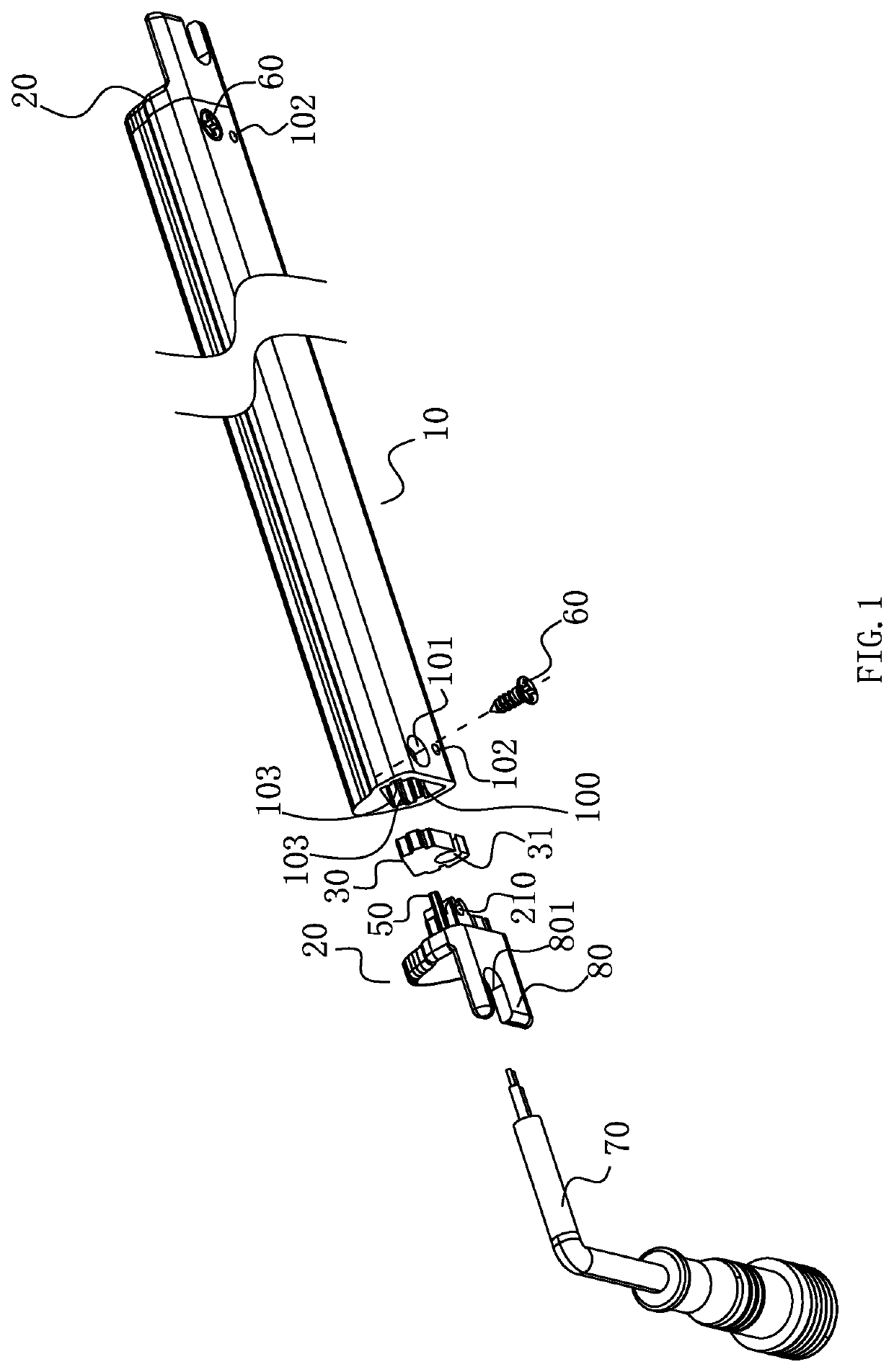
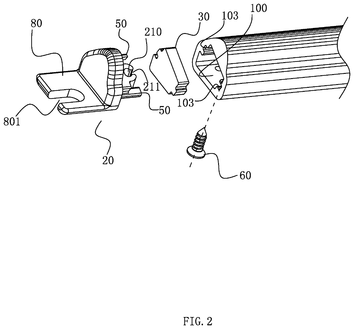
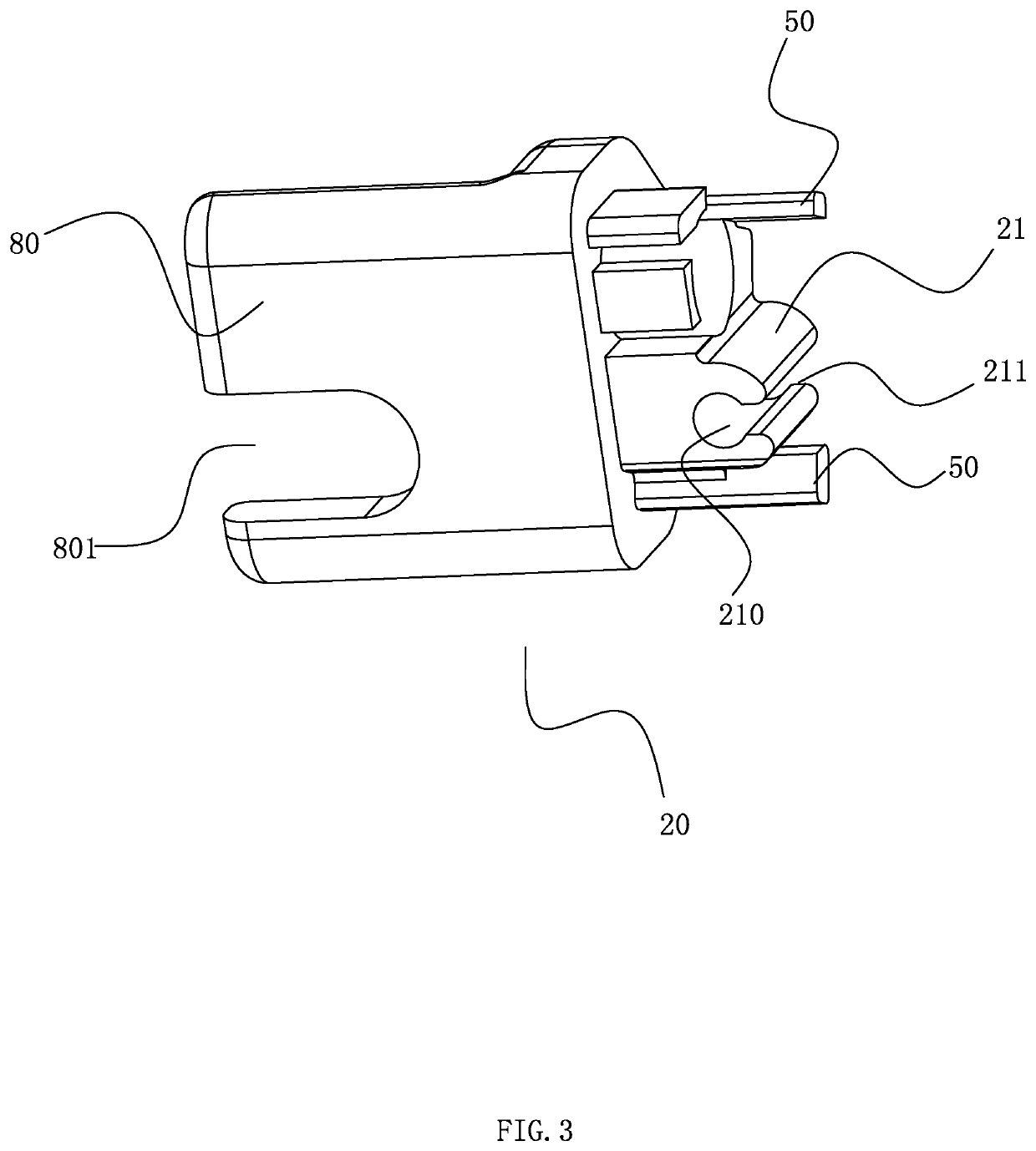
[0026]As shown in FIG. 1 to FIG. 5, the LED lamp comprises a strip housing 10, a sealing member 30 and a sealing end cover 20, wherein the strip housing 10 has an inner cavity for accommodating the lamp body and at least one end is formed into a opening 100 for loading the lamp body, specifically, in the present embodiment, the strip housing 10 forms two openings 100 at both ends thereof, and the sealing end cover 20 is sealed at the two openings 100. A sealing member 30 is embedded in the opening 100. The sealing member 30 and the inner space of the opening 100 have the same cross section perpendicular to the length direction of the strip housing 10. It can be understood that the outer periphery of the sealing member 30 can be sealed and attac...


PUM


Abstract

The present invention relates to an LED lamp comprising a strip housing having an inner cavity for accommodating a lamp body and at least at one end forming a opening for loading the lamp body; and a sealing end cover for sealing the opening; a sealing member is embedded in the opening, and the sealing member and the inner space of the opening have the same cross section perpendicular to the length direction of the strip housing; the sealing member and the sealing end cover are spaced apart to form a sealing cavity for injecting the sealant. the LED lamp of the invention on the one hand realizes the first waterproof protection of the end part by the sealing member, and on the other hand realizes the second waterproof protection through the sealant layer formed by pouring sealant between the sealing member and the sealing end cover, so the LED lamp has higher waterproof rating than the existing lamps and can be conveniently applied to a humid device such as refrigerator, refrigerator, freezer and vending machine.

Description

RELATED APPLICATION[0001]This application claims priority to a Chinese Patent Application No. CN 201810561941.0, filed on May 31, 2018.FIELD OF THE TECHNOLOGY[0002]The present invention relates to lighting technology, with particular emphasis on a LED lamp.BACKGROUND OF THE INVENTION[0003]At present, in order to be able to provide a better view, and to facilitate users to select items and take objects, the current manufacturers of refrigerators or showcases will install corresponding lights inside the products.[0004]In the prior art, the lighting in the refrigerator or the showcase is different from the environment in which the ordinary lamp is used, and fog and water vapor are generated due to the temperature difference. The lamp without the waterproof sealing structure is easily damaged in the freezer for a long time, and the using life of the lamp is shortened.[0005]In addition, most of the lighting sources used in the market for refrigerators, refrigerators, freezers and vending...

Claims


Application Information

Patent Timeline
Patent Type & Authority Applications(United States)
IPC IPC(8): F21V31/00F21K9/272F21V23/00F21V5/04F21K9/69
CPCF21Y2103/10F21V5/04F21K9/272F21V31/005F21V23/001F21Y2115/10F21K9/69F21S8/00F21V17/12F21V19/0015F21V23/06F21W2131/405F25D27/00A47F3/0426F21S4/28F21V15/015F21W2131/305
Inventor XUE, YUANFANGZHENG, ZHAOYONG
Owner SELF ELECTRONICS CO LTD
Why Eureka
Try Eureka