Connector

Active Publication Date: 2019-12-05
SUMITOMO WIRING SYST LTD
View PDF0 Cites 5 Cited by
  • Summary
  • Abstract
  • Description
  • Claims
  • Application Information

AI Technical Summary

Benefits of technology

[0012]The connector body may include a prying preventing portion configured to prevent prying of the tab by projecting into the receptacle from a back surface side of the receptacle, and the restricting surface is provided on the prying preventing portion. According to this configuration, the connector body need not have a dedicated structure for the restricting surface and the structure thereof can be simplified.
[0013]The mating connector may include a recess configured to receive the prying preventing portion, and the receiving portion may be provided on an inner surface of the recess. Accordingly, the resilient locking piece is not made larger, and the recess need not have a large opening. Thus, structural restrictions around the recess in the mating connector can be reduced.
[0014]The connector body may include a housing having the receptacle and a front retainer config

Problems solved by technology

At this time, if a locking force of the resilient locking piece for locking the locking portion is weak, the resilient locking piece may inadvertently disengage from

Method used


Image

  • Connector
  • Connector
  • Connector

Examples


Embodiment Construction

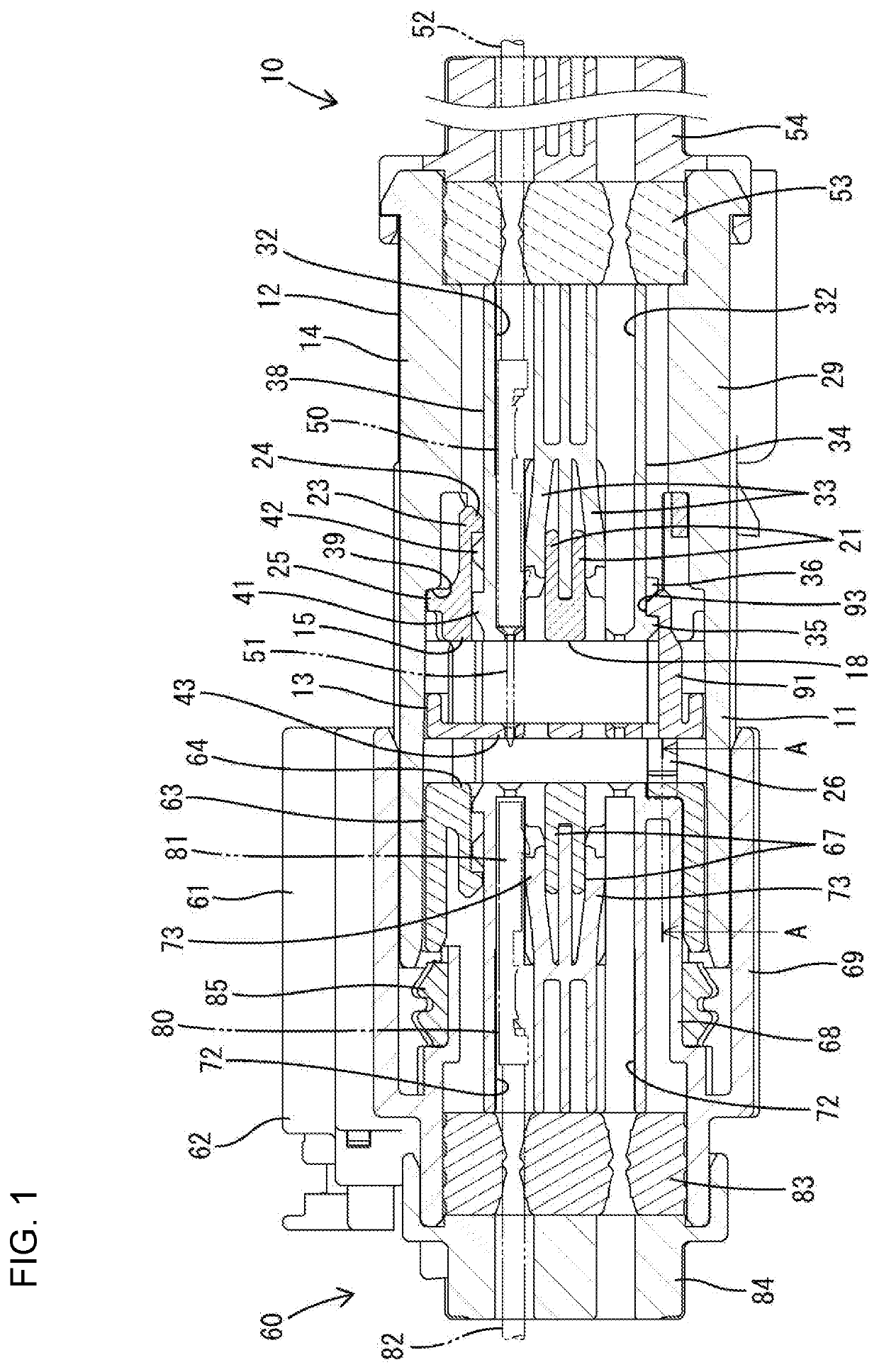
[0031]An embodiment is described on the basis of the drawings. As shown in FIG. 1, this embodiment is composed of male and female connectors 10, 60 connectable to each other. The male connector 10 includes a connector body 12 having a receptacle 11 and a moving plate 13 arranged movably in the receptacle 11. The female connector 60 is a mating connector and includes a mating connector body 61 having a part fittable into the receptacle 11. In the following description, surface sides of the connectors 10, 60 facing each other at the start of connection are referred to as front ends concerning a front-rear direction and a vertical direction is based on each drawing.

[0032]60>

[0033]The mating connector body 61 is made of synthetic resin and includes, as shown in FIGS. 15 and 16, a mating housing 62 and a separate mating front retainer 63 to be mounted into the mating housing 62.

[0034]The mating front retainer 63 includes a mating front wall 64 for covering the front surface of the mating...


PUM


Abstract

A moving plate (13) is inserted into a receptacle (11) of a connector body (12) and movable between a partial locking position and a connection position and includes partial locking portions (91) and resilient locking pieces (46). The partial locking portions (91) restrict movement of the moving plate (13) to the connection position. The resilient locking pieces (46) lock to receiving portions (75) of a mating connector (60) and allow movement from the connection position to the partial locking position by being kept locked to the receiving portions (75) while separating the mating connector from the receptacle (11). The connector body (12) has restricting surfaces (28) to restrict deflection of the resilient locking pieces (46) until a riding amount of the partial locking portions (91) on second interfering portions (36) is a maximum when the moving plate (13) returns from the connection position to the partial locking position.

Description

BACKGROUNDField of the Invention[0001]The invention relates to a connector.Related Art[0002]Japanese Unexamined Patent Publication No. 2017-134981 discloses a connector with a male housing having a receptacle, a terminal fitting having a tab projecting into the receptacle and a moving plate inserted into the receptacle. The moving plate is movable between an initial position and a connection position backward of the initial position with the tab positioned.[0003]The moving plate is pressed by a female housing of a mating connector that is fit into the receptacle and is moved from the initial position to the connection position. On the other hand, the moving plate is pulled back from the connection position to the initial position when the female housing is separated from the receptacle.[0004]The moving plate includes a holding protrusion and a resilient locking piece projecting forward on a side closer to an end part than the holding protrusion.[0005]The male housing includes an ini...

Claims


Application Information

Patent Timeline
IPC IPC(8): H01R13/631H01R13/453H01R13/506H01R13/627H01R13/52
CPCH01R13/631H01R13/5219H01R2107/00H01R13/6271H01R13/4538H01R13/506H01R13/627H01R13/629H01R13/639H01R13/64H01R13/6275
Inventor HIROTA, MASANORI
Owner SUMITOMO WIRING SYST LTD
Why Eureka
Try Eureka