Tri-redundant data center power supply system

Active Publication Date: 2019-12-05
SWITCH
View PDF0 Cites 1 Cited by
  • Summary
  • Abstract
  • Description
  • Claims
  • Application Information

AI Technical Summary

Benefits of technology

The invention is an integrated data center that has efficient cooling and wire routing. This means that the center provides better maintenance and management of its equipment.

Problems solved by technology

These units, however, are not located in standardized, accessible and relatively convenient positions relative to the facility should any of the units need to be accessed and / or removed for repair or replacement.
Further, these units are not themselves created using an intentionally transportable design.

Method used


Image

  • Tri-redundant data center power supply system
  • Tri-redundant data center power supply system
  • Tri-redundant data center power supply system

Examples


Embodiment Construction

[0033]The present invention provides data center or co-location facility designs and methods of making and using the same. The data center or co-location facility designs have certain features that will be apparent herein and which allow many advantages in terms of efficient use of space, efficient modular structures that allow for efficiency in the set-up of co-location facility and the set-up of the electronics equipment in the facility, as well as efficient air-conditioning within the facility. Each of these features has aspects that are distinct on their own, and combinations of these features also exist that are also unique.

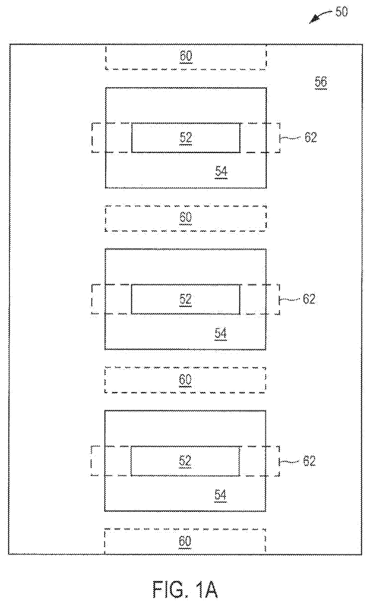
[0034]FIG. 1(a) illustrates a floor design used in a data center or co-location facility according to the present invention. The preferred embodiment discussed herein uses parallel rows of equipment configured back-to back so that each row of equipment generally forces the heat from the electronic equipment towards a hot aisle, thus also establishing a cold ...


PUM


Abstract

Described herein is an integrated data center that provides for efficient powering and cooling, as well as efficient wire routing.

Description

BACKGROUND1. Priority Claim[0001]This application is a continuation in part of U.S. patent application Ser. No. 15 / 663,169 entitled “Facility Including Externally Disposed Data Center Air Handling Units” filed Jul. 28, 2017, which is a continuation of U.S. patent application Ser. No. 15 / 291,005 entitled “Facility Including Externally Disposed Data Center Air Handling Units” filed Oct. 11, 2016, which is a continuation of U.S. patent application Ser. No. 13 / 732,942 entitled “Electronics Equipment Data Center or Co-Location Facility Designs and Methods of Making and Using the Same” filed Jan. 2, 2013, which is a continuation of U.S. patent application Ser. No. 12 / 384,109 entitled “Electronic Equipment Data Center or Co-Location Facility Designs and Methods of Making and Using the Same” filed Mar. 30, 2009, which claims priority to U.S. Provisional Patent Application No. 61 / 040,636 entitled “Electronic Equipment Data Center or Co-Location Facility Designs and Methods of Making and Usin...

Claims


Application Information

Patent Timeline
IPC IPC(8): H05K13/00H05K7/20H05K5/02F25B25/00G06F11/30G06F1/20
CPCH05K7/20709H05K5/0213G06F11/2015F25B2700/173H05K7/20145G06F2200/201G06F1/20H05K13/00G06F11/3062H05K7/20745F25B25/005H05K7/1497G06F11/3058G06F11/3006H02J2310/16
Inventor ROY, ROB
Owner SWITCH
Why Eureka
Try Eureka