

Device For Degreasing A Full-Thickness Skin Transplant
- Summary
- Abstract
- Description
- Claims
- Application Information
AI Technical Summary
Benefits of technology
Problems solved by technology
Method used
Image

Examples
Embodiment Construction
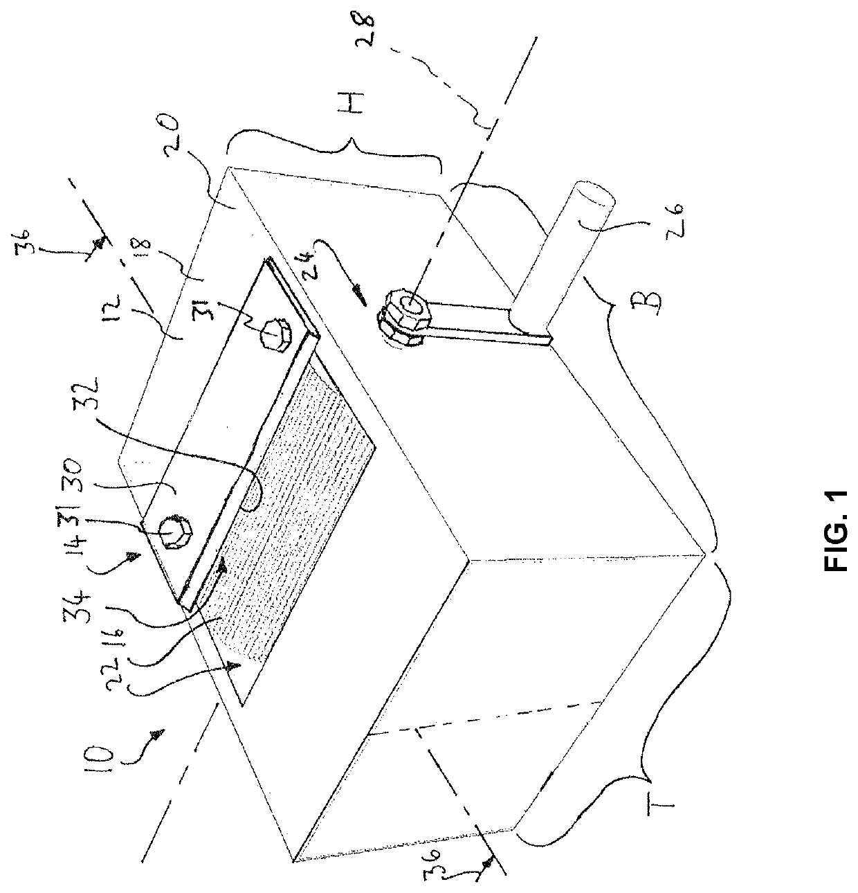
[0064]FIG. 1 shows a device 10 according to the invention for degreasing a full-thickness skin transplant. The device 10 comprises a base body 12, a cutting unit 14 and a drawing roller 16.
[0065]The base body 12 here essentially comprises a rectangular housing 18 made of stainless steel. In the present exemplary embodiment of the invention, the stainless steel housing has a width B of 30 cm in this example, a depth T of 20 cm in this example and a height H, also of 20 cm in this example. These measurements, however, are in no way to be understood as limiting, but only illustrate the presently described embodiment as an example. The present invention is also not limited to a base body 12 having the design of the present one, in particular to a housing 18 having the measurements indicated here. For example, the drawing roller 16 can also be provided in a device 10 completely without a housing 18.
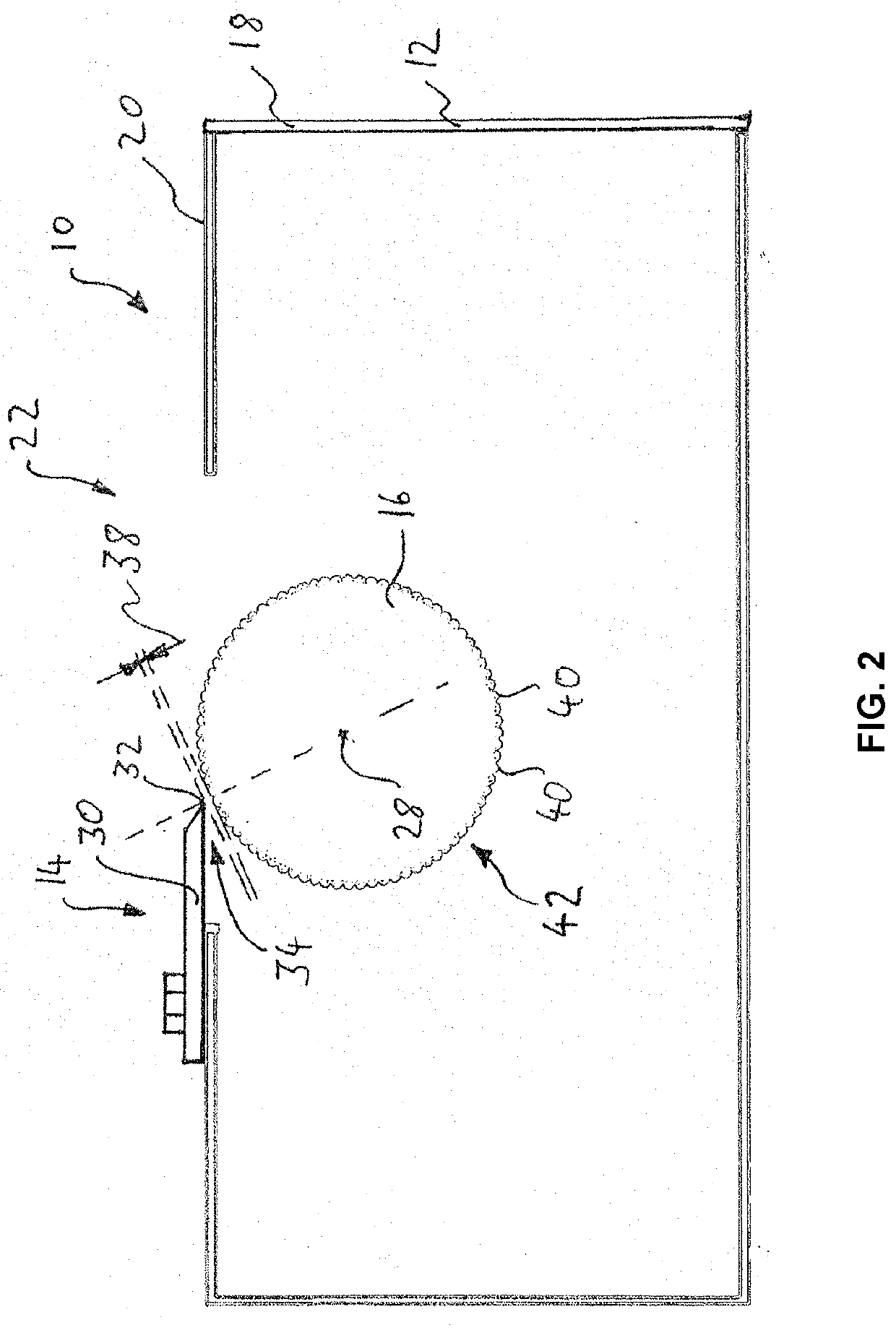
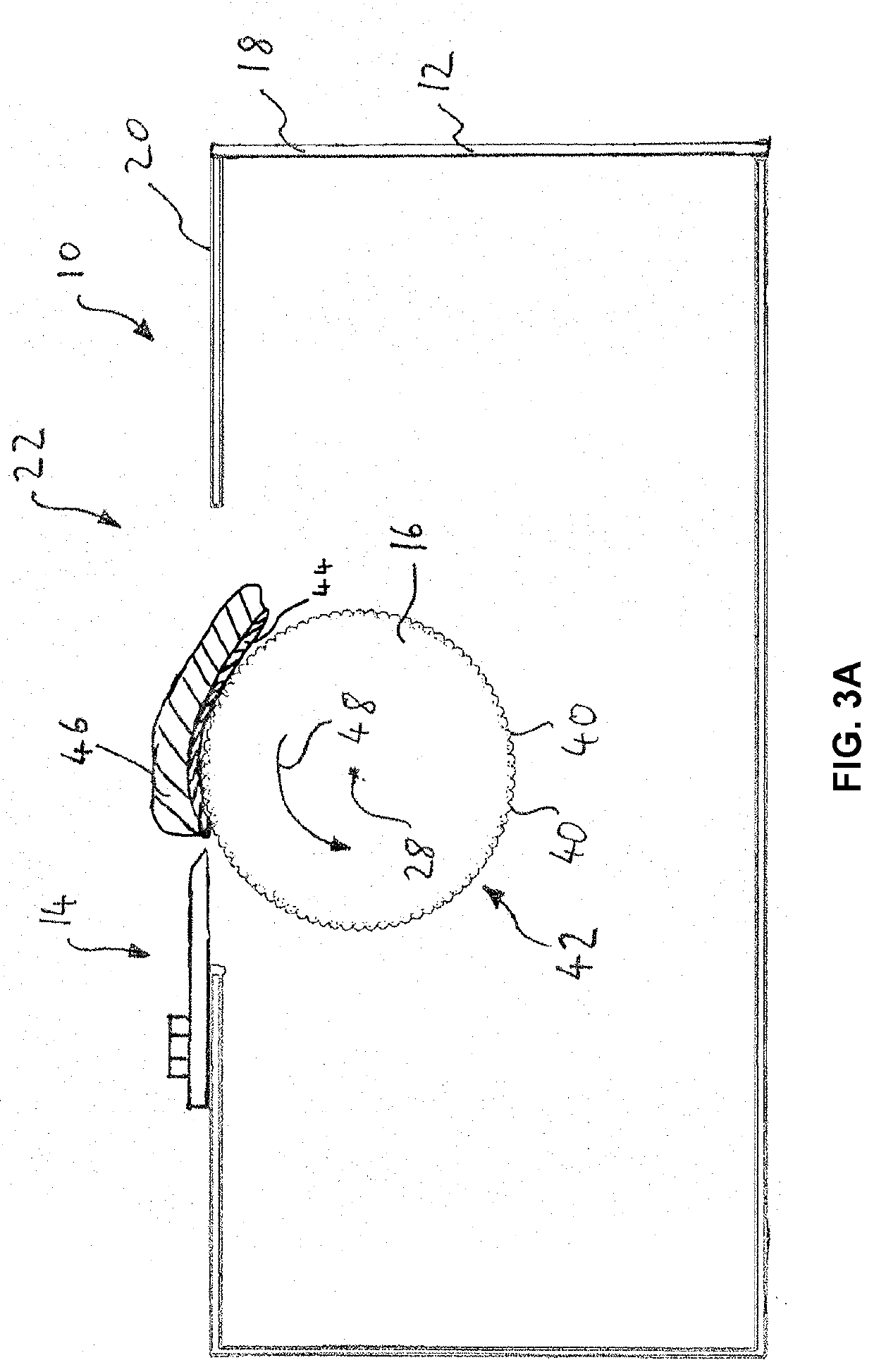
[0066]The housing 18 has an opening 22 in a top side 20. Looking into the opening 22, the ...
PUM
 Abstract
Description
Claims
Application Information