

A novel flexible microfluidic meshwork for glaucoma surgery
- Summary
- Abstract
- Description
- Claims
- Application Information
AI Technical Summary
Benefits of technology
Problems solved by technology
Method used
Image

Examples
experimental examples
[0055]The invention is further described in detail by reference to the following experimental examples. These examples are provided for purposes of illustration only, and are not intended to be limiting unless otherwise specified. Thus, the invention should in no way be construed as being limited to the following examples, but rather, should be construed to encompass any and all variations which become evident as a result of the teaching provided herein.
[0056]Without further description, it is believed that one of ordinary skill in the art can, using the preceding description and the following illustrative examples, make and utilize the compounds of the present invention and practice the claimed methods. The following working examples therefore, specifically point out exemplary embodiments of the present invention, and are not to be construed as limiting in any way the remainder of the disclosure.
example 1
lexible Microfluidic Meshwork to Reduce Fibrosis in Glaucoma Surgery
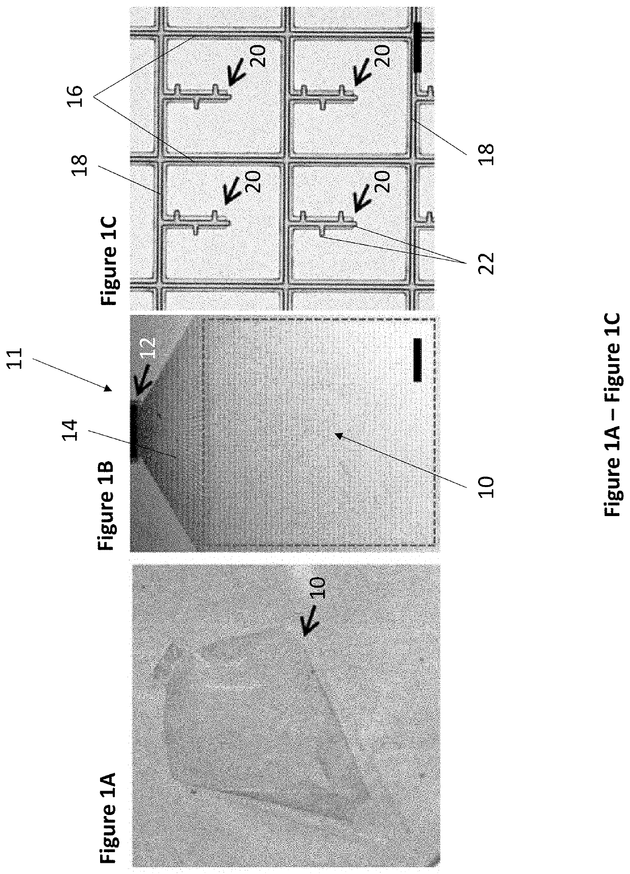
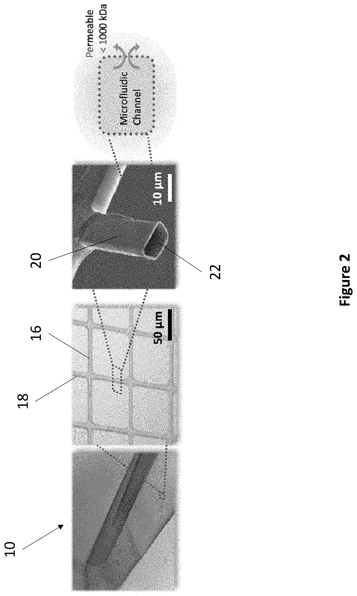
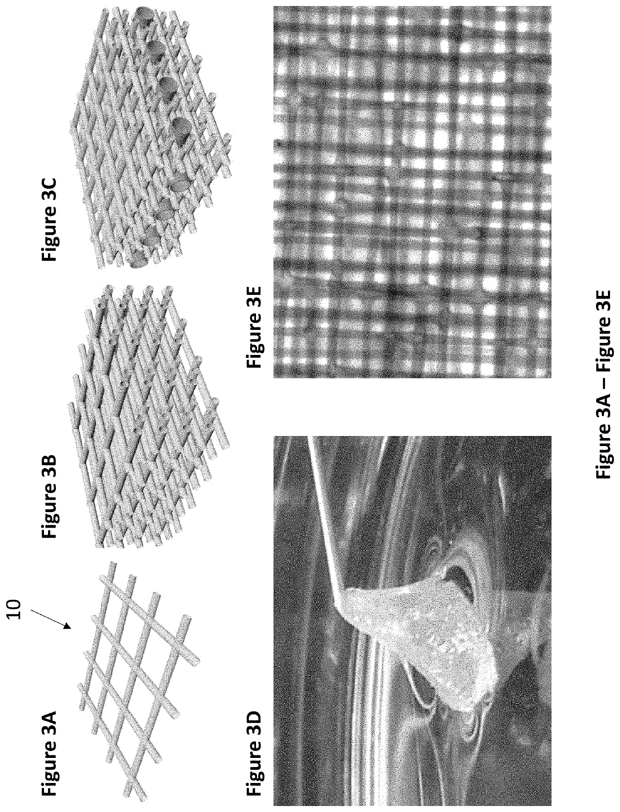
[0057]The following study presents the concept for a modified GDI (FIG. 7). The device design is based on that of the conventional GDI; however, the solid plate was replaced with a microfluidic meshwork in the fluid drainage region. The design of the meshwork was inspired by recently developed brain implants that can suppress chronic foreign body reactions (Xie C et al., Nature materials 14.12 (2015): 1286-1292). Two key features of the brain implants were incorporated into the microfluidic meshwork design. Firstly, it consists of interconnected, cellular-dimensioned microfluidic channels that can conduct fluid. Secondly, it is ultra-flexible and conforms to the curvature and movement of the eye tissue after implantation. It was hypothesized that these two features combined minimize fibrotic tissue formation around the meshwork, and therefore reduce the risk of failure of the drainage implants. In this work, as the ...
PUM
 Abstract
Description
Claims
Application Information